
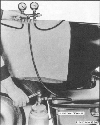
Fig. 12. If Pressure is Below Normal
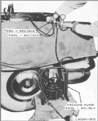
Fig. 13. Connect Pump and Evacuate
Attach Freon Tank - Open Tank Valve
System to Approximately 27"
Tool - ACL53-3, counterclockwise and slowly
release system pressure through manifold
center hose.
8. When both high and low pressure gauges
of the
Pressure Test Gauge Manifold read "O"
P.S.I.
attach manifold center hose to Vacuum
Pump, Tool
- ACL53-1 and evacuate until system reaches
27"
of mercury. See figure 13. CAUTION: Do
not
connect center hose of the Pressure Test
Gauge
Manifold to Vacuum Pump when there is
still
pressure in system.
9. Turn low pressure gauge valve of the
Pressure
Test Gauge Manifold, Tool - ACL53-3
clockwise until fully closed, then disconnect
vacuum pump.
10.
Invert Fr eon tank on a scale and attach
center
hose of the Pressure Test Gauge Manifold
to
Freon tank. (Scale will measure amount
of
Freon going into system. Fully charged
system
has approximately 7 lbs.)
11. Open Freon tank valve.
12. By intermittently opening and closing
low
pressure valve of the Pres-sure Test Gauge
Manifold, Tool
- ACL53-3, (approximately 1/4 turn) allow
liquid Freon to be drawn into system until
pressure reaches 45 P.S.I. See figure
14.
13. Close low pressure valve of the Pressure
Test
Gauge Manifold, Tool - ACL53-3, start
engine and run at 1500 R.P.M.