
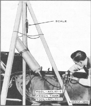
Fig. 14. Bring Pressure to 45 P.S.I.
With engine running at 1500 R.P.M.
intermittently open and close low pressure
valve of the Pressure Test Gauge Manifold
(approximately 1/4 turn), and allow liquid
Freon to flow into system. CAUTION: Gauge
manifold will get cold, however, excessive
frosting indicates too fast a flow.
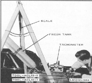
When system is fully charged, there will be no
bubbles visible in sight gauge, the high pressure
gauge will read between 90 and 120 P.S.I., the
low pressure gauge will read between 15 and
25 P.S.I. and there will be approximately 7 lbs.
of Freon in the system. See figure 15.
Turn high pressure valve, located on condenser
and low pressure valve, located on right front
fender apron, counterclockwise to the fully
opened position, using Tool - ACL53-5.
Fig. 15. Charge the System
17.
Turn off Fr eon tank valve.
18. Disconnect and remove Pressure Test Gauge
Manifold, Too1- ACL53-3 from Freon tank and
low and high pressure valve service ports. Cap
gauge hoses and service ports, re-place low and
high pressure valve stem protector caps.
1. Install Pressure Test Gauge Manifold, Tool -
ACL53-3 with both gauge valves turned in the
full clockwise position, so that the high
pressure gauge hose is connected to the high
pressure valve service port, and the low
pressure gauge hose is connected to the low
pressure valve service port.
2. Turn low pressure valve located on right front
fender apron,
and high pressure valve located
on condenser, 1-1/2 turns in the clockwise
direction, using
Tool - ACL53-5. Both gauges
will read neutral system pressure.
(Approximately 50 - 75
14.
15.
16.
PUMP-DOWN PROCEDURE