
NOTE: If the system pressure is low, or there
is no pressure, this step may be omitted.
5. Loosen the valve fitting on the flexible low
pressure hose, running from the compressor to
the low pressure valve located on right front fender
apron, with Tool-ACL53-7 and al-low refrigerant
to exhaust. When refrigerant is exhausted,
disconnect hose and cap hose and fitting
immediately.
6. Disconnect flexible high pressure hose,
running from the compressor to the high
pressure valve located on the condenser, at the
compressor, using Tool - ACL53-7. Cap
compressor fitting and hose fitting immediately.
9. Remove oil filler cap and oil level indicator.
10. Remove exhaust manifold cross-over pipe and
heater hose clamp attached to lower right
stud on R.H. exhaust manifold.
11. Remove cap screw from compressor which
secures the oil level indicator tube bracket to
the compressor.
12. Remove cap screw from compressor which
secures the compressor to manifold bracket.
13. Loosen compressor head cap screw sufficiently
to remove the bracket supporting the heater
hose and re tighten cap screw. Torque to 20
lbs. ft.
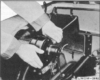
7. Disconnect defroster blower motor bullet
connectors, heater delivery chamber clips, and turn
blower motor clockwise and remove entire
assembly. See figure 19.
Fig. 19. Removing Heater Blower Motor and
Duct Assembly
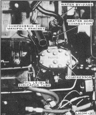
8. Disconnect the water by-pass tube at the water
outlet connection.
14. Disconnect the heater hose connection at the
water pump and move out of way. See figure
20.
Fig. 20. Preparing for Removal of
Compressor
12