
15. Remove compressor belt from compressor
pulley.
16. Remove generator.
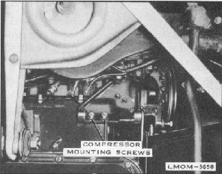
Remove the two cap screws securing the
compressor mounting pad to the cylinder block
and allow compressor to rest against the
cylinder block and upper front suspension arm.
See figure 21. NOTE: One attaching stud taps
into engine water jacket.
Fig. 21. Compressor Mounting Cap
Screws
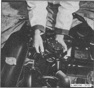
Lift compressor, with high pres-sure hose
attached, from engine compartment. See figure
22. NOTE: When replacing defective
compressor, remove high pressure hose and
install immediately on re-placement
compressor. Cap fitting on defective
compressor.
3.
INSTALLATION OF COMPRESSOR
ASSEMBLY
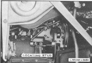
1. Install a 3/8" x 2" stud in compres-
sor pad rear mounting hole in engine
4.
block. NOTE: This is a locating
stud for mounting purposes to be
removed later.
5.
Fig. 22. Lifting Compressor from Engine
Compartment
2. Position compressor assembly on locating stud
and replace cap screw in forward mounting
pad hole. See figure 23.
Fig. 23. Locating Compressor on Stud
Remove locating stud and replace rear cap
screw. (Torque screws to 23 - 28 lbs. ft.)
NOTE: Apply water sealer to rear cap screw
before installation.
Install generator in accordance with generator
installation procedure.
Install idler and support assembly
18.
17