
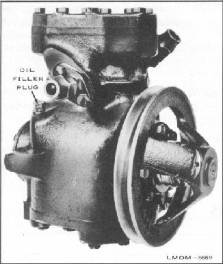
Fig. 33. Compressor Oil Filter
Plug Location
5. Remove blower and motor assembly. NOTE: To
install, reverse the removal procedure.
REMOVAL OF R.H.
MOTOR
1. Remove the two wing nuts securing inspection
cover to evaporator assembly, and remove cover.
2. Disconnect electrical wires at bullet connections.
3. Remove the four screws securing the blower
assembly to the side of evaporator.
4. Remove blower and motor assembly. NOTE: To
install, reverse the removal procedure.
5. Release "Pumped Down" pressure by opening
the shut off valves in the following order. Turn all
valves counterclockwise to open.
1. Open receiver shut off valve.
PRE-DELIVERY
1. Make a visual inspection of all assemblies to
make sure they are tightly mounted. Also check for
2. When no more liquid Freon is flowing past
sight gauge, open low pressure valve.
(a) Oil around connections, indicating a leak.
3. Open high pressure valve. REMOVAL OF
L.H. BLOWER AND MOTOR
ASSEMBLY 1. Disconnect electrical wires at
bullet
connections.
(b) Oil around the compressor head bolts, or
filler plug indicating a leak.
(c) Cracked sight gauge in evaporator
assembly.
2. Remove flexible hose at duct.
(d) Loose compressor drive belt.
3. Remove hex. head screw securing blower
assembly to wheelhouse.
4. Remove three screws securing blower assembly
to package tray.
(e) Disconnected or improperly connected
Bowden wire at modulator. Check for
freedom of movement.
2. Check entire system for leaks.
23