likely to be damaged during disassembly. The following disassembly procedure includes instructions to discard the parts for which replacements are included in the Master Repair Kit.
4. DISASSEMBLY 885-FFC
The following list contains the component parts of the Model 885-FFC Airhorn Assembly in the order of their removal. The following disassembly procedure also includes the disassembly of the automatic choke control mechanism. The automatic choke control may be found mounted on the intake manifold instead of on the side of the carburetor air inlet in some models. It is recommended that this divorced choke be overhauled at the same time the carburetor is overhauled. During disassembly discard all gaskets, also all parts which have replacements in the Master Repair Kit.
* Automatic Choke
A. DISASSEMBLY - AIRHORN ASSEMBLY


|
we
°
o,,
,SOSJS
SDtC~
AIRHORN DISASSEMBLY
k | ||
|
1 |
1 |
Fast Idle Rod Retainers (2) |
|
1 |
2 |
Fast Idle Rod Washer |
|
1 |
3 |
Fast Idle Rod |
|
2 |
4 |
Airhorn Screws (5) |
|
1 |
5 |
Airhorn Gasket |
|
1 |
6 |
Choke Lever |
|
3 |
7 |
Thermostat Housing Screws and Re |
|
tainers (3) | ||
|
4 |
8 |
Thermostat Housing Cover Assembly |
|
4 |
9 |
Thermostat Housing Gasket |
|
4 |
10 |
Choke Housing Plate |
|
1 |
11 |
Choke Lever Nut, Lockwasher and |
|
Spacer | ||
|
1 |
12 |
Choke Housing Screws (2) |
|
1 |
13 |
Choke Housing * |
|
1 |
14 |
Choke Shaft and Lever Assembly |
|
1 |
15 |
Choke Housing Gasket * |
|
4 |
16 |
Piston Lever Assembly |
|
5 |
17 |
Choke Linkage |
|
1 |
18 |
Choke Plate Screws (2) |
|
1 |
19 |
Choke Plate |
|
1 |
20 |
Choke Shaft |
|
1 |
21 |
Bowl Vent Screws and Lockwasher (2) |
|
1 |
22 |
Bowl Vent |
|
1 |
23 |
Air Bleed Screen - If Included |
|
24 |
Power Valve Assembly | |
1. Remove the two fast idle rod retainers connecting the fast idle rod to the fast idle cam
8
CARBURETOR MODELS 885-FF & 885-FFG
and choke lever. Then remove the fast idle rod washer and fast idle rod.
Figure 2. Removing Air Horn Screws
2. Remove the five airhorn screws. Lift off the airhorn assembly from the main body and discard the airhorn to throttle body gasket.
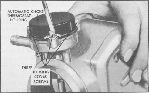
Figure 3. Removing Automatic Choke Cover Screws
3. If the model you are disassembling has a choke lever assembly loosen the screw and remove this lever assembly.
4. Remove the three thermostat cover screws and retainers, then remove the thermostat housing cover assembly. Remove the choke lever nut, Lokwasher and spacer.
5. Remove piston and lever assembly.
6. Remove the choke housing screws and lift the housing off the airhorn. Remove and discard the housing gasket.
NOTE
On some models, the lever and piston assembly is an integral part of the choke shaft.
AIR HORN SCREWS