
8. REBUILDING - MODEL 885-FFG
A. Reassembly - Throttle Body Assembly - Model 885-FFG
1. Reassembly of throttle body
a. Slip the throttle shaft with the attached bearing into the throttle body and install the wire throttle shaft retainer with the bent-in sides of the retainer pressing against the bearing. Press the separate throttle shaft bearing into position on the governor side of the throttle body.
b. Referring to the lines and figures scribed on the throttle plates and throttle body during disassembly, install the two throttle plates, using four new throttle plate screws. Install the four throttle plate screws snugly but do not tighten them. Check to be sure no binding is present when the throttle shaft is rotated. With the throttle plates closed, hold the throttle body up to the light. Little or no light should show between the throttle plates and the throttle bores of the carburetor. When the throttle plates are properly aligned, tighten the four throttle plate screws and stake them to prevent loosening. Use any approved carburetor staking tool. If it is necessary to use an impact type of staking tool, be sure to back up the heads of the throttle plate screws to prevent bending the throttle shaft when staking the screws.
assembly in place on the throttle body, while holding the pump operating lever of the throttle operating shaft and lever assembly in the down position. When this assembly is properly installed, it should hold the throttle plates closed when the pump operating lever is up, but should permit the plates to move freely when the lever is down.
h. Install the throttle lever and tighten the throttle lever clamp screw. Insert the throttle lever pin.
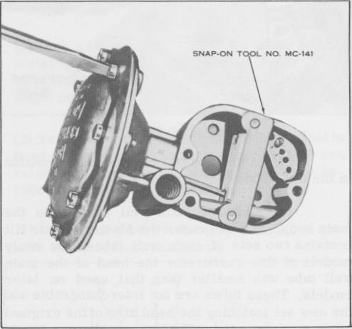
Figure 39. Installing Governor Diaphragm Cover
c. Install the pump rod felt packing and retainer. Stake the retainer in position.
d. Invert the throttle body and install the distributor check valve retainer -- if included.
e. Install the throttle stop screw and spring. Turn the screw in until its tip contacts the tab at the end of the throttle shaft lever, holding the throttle plates just short of their closed position.
f. Install the two idle adjusting needles and springs. Turn gently until the needles seat, then, turn them back one complete turn. Do not force the needles against its seat, as this will groove the tips of the needles, making it impossible to correctly adjust the idle mixture.
g. Place the throttle operating shaft and lever assembly in position in the throttle operating shaft housing. Insert the two screws and lockwashers in the housing. Fit the new gasket over the ends of the screws and, with the throttle plates held in the closed position, set the
2. Reassembly of Governor
a. Place the new diaphragm and rod assembly in the governor , housing. Be sure that all the holes in the diaphragm are aligned with the threaded holes in the rim of the governor housing. The bent ends of the rod should point out. Place the diaphragm cover in position, being sure the vacuum passage holes in the governor housing, diaphragm, and diaphragm cover are all correctly aligned. Insert the eight diaphragm cover screws and lockwashers, spacing evenly the three screws drilled for lock wiring. Turn the screws in until the flanges nearly meet but do not tighten the screws. Place the governor diaphragm gauge, Snap-On Tool No. MC-141, on the governor housing as shown in the illustration and hook the end of the diaphragm rod into the slot provided in the gauge. Tighten the eight diaphragm cover screws securely before removing the gauge. This procedure will stretch the diaphragm sufficiently to insure full travel of the diaphragm and proper governor operation. Install anew safety wire and seal to the three diaphragm cover screws drilled for lockwiring.
-22