| 38 of 40 |  |
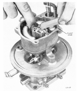
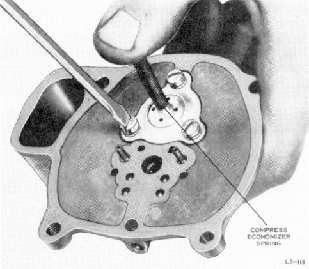
FIGURE 55. CHECKING FLOAT LEVEL
7. Lift the float to completely close
the fuel
inlet valve. Holding the floats in
the closed po
sition, place the float gage across
the float cham
ber, resting one end on the rim of
the float chamber
and the other on the center of the
main body. The
tab on the gauge should just touch
the flat top sur
face of the float at a point on
the flat top surface
farthest from the fuel inlet valve.
Check both
floats in this manner. If one of
the floats is lower
than the other, slightly bend the
portion of the float
lever adjacent to the float to correct
the mis
alignment. A light pressure must
be used, as a
small bend will result in a considerable
change in
the height of the toe of the float.
The float level
can be adjusted by bending the tab
on the float
lever which contacts the fuel inlet
needle. Bend
the tab up to lower the floats,
or down to raise
them. To bend the tab, fit the slot
at the end of the
Snap-On Tool No. MC-140 over the
tab and apply
8. Install the two new idle tubes.
To insure
proper metering, turn the'idle tubes
down tightly
on their seats.
9. Install the new accelerating
pump discharge
needle.
10. Install the two new main well
tubes.
11. Compress the accelerating pump
spring
and washer on the new accelerating
pump piston
and slip the accelerating pump operating
rod
through the slot in the piston stem.
Slip the pump
return spring over the pump operating
rod.
12. Carefully install the pump assembly.
Do
not allow the leather piston to
catch on the edge
of the pump chamber. On the carburetors
having
the type of pump operating rod seal
which fits
around the rod on the top surface
of the throttle
body, slide the spring, washer,
and seal, in that
order, on the pump operating rod,
and install the
snap ring retainer at the lower
end of the rod.
FIGURE 56. INSTALLING ECONOMIZER
DIAPHRAGM
AND STEM ASSEMBLY
13. Place the new economizer diaphragm
assembly on the main body cover
and carefully re
place the economizer clamp, screws,
and lock
washers.
CAUTION
To insure full travel of the economizer
stem, the screws should be tightened
while
the economizer stem is in the compressed
position. (figure 56).
E. Reassembly - Main Body to Throttle
Body
- All Carburetors.
1. Over the accelerating pump operating
rod, place, in this order, the
pump rod seal re
tainer spring, pump rod seal retainer
and pump
rod seal. On earlier models with
a recessed hole
for the pump rod seal, a modification
kit can
be purchased to convert to the
new type of seal.
Fit a new main body to throttle
body gasket on
the protruding foot of the main
body. Place the
main body assembly in position
on the throttle