(2) Mechanical - A secondary throttle
shaft lever attached to the primary throttle shaft
opens the secondary plates in relation to prede
termined engine requirements. |
|
|
D. OVER-RUN CONTROL VALVE -Elimin
ates popping back on deceleration. (Not on all
models.) |
|
| |
|
|
|
|
|
|
|
| |
|
E. ANTI-BACKFIRE VALVE - Eliminates
popping back on deceleration. (Not included on
all models.) |
|
| |
|
|
|
|
|
|
|
|
|
|
|
| |
|
B. SPARK ADVANCE - |
|
|
|
|
|
|
|
| |
|
|
|
|
|
|
|
|
|
|
|
| |
|
|
|
|
|
|
|
|
|
|
|
|
|
|
|
|
(1) Distributor - Centrifugal - Utilizes
vacuum for initial advance at off idle and centri
fugal force throughout the rest of the engine range. |
|
|
|
|
|
|
|
|
| |
|
F. GOVERNOR - INTERNAL VACUUM
TYPE - Venturi and manifold vacuum acts on a
governor diaphragm to close the throttle plates
when governing speed is reached. |
|
| |
|
|
|
|
|
|
|
|
|
|
|
| |
|
|
|
|
|
|
|
|
|
|
|
|
|
|
|
|
(2) Distributor - Pressure - Utilizes
changes in air pressure within the carburetor to
control spark timing to satisfy engine speed and
load conditions. |
|
|
|
|
|
|
|
|
| |
|
G. GOVERNOR - EXTERNAL VACUUM
TYPE - Uses an external source of vacuum
acting on the governor diaphragm when governing
speed is reached. |
|
| |
|
|
|
|
|
|
|
|
|
|
|
| |
|
|
|
|
|
|
|
|
|
|
|
|
|
|
|
|
C. VACUUM OPERATED AUTOMATIC
TRANSMISSION -Uses manifold vacuum to control
the shift points in the transmission. |
|
|
H. GOVERNOR - MECHANICAL - A separate
governor controls the throttle plates of the car
buretor. |
|
| |
|
|
|
|
|
|
|
|
|
|
|
|
|
|
|
|
| |
|
|
|
|
|
|
|
OPERATION |
|
|
|
|
| |
|
|
|
|
|
|
|
|
|
|
|
|
|
|
|
|
| 1. PRIMARY SYSTEM |
|
|
|
|
|
|
|
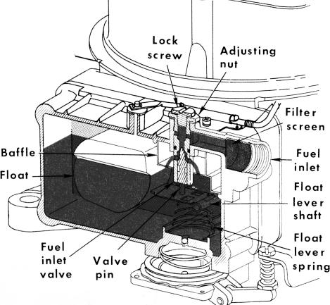
which rises and falls with the fuel level. As the
fuel level drops, the float drops, opening the needle
valve to allow fuel to enter the float chamber.
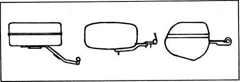
There have been three different shape floats used
in these carburetors. These floats are NOT
interchangeable. |
| |
|
|
|
|
|
|
|
|
|
|
A. FUEL INLET SYSTEM - The fuel enters
the fuel bowl thru a filter screen and into the fuel
inlet valve which is frequently referred to as the
fuel inlet needle and seat assembly. The amount
of fuel entering the fuel bowl is determined by the
space between the top of the moveable needle and
its seat and also by the pressure from the fuel
pump. Movement of the needle in relation to the
seat is controlled by the float and lever assembly |
|
|
| |
|
|
|
|
|
|
|
| |
|
|
When the fuel reaches a specified level, the
float moves the needle valve to a position in its
seat where it restricts the flow of fuel, admitting
only enough to replace that being used. Any slight
change in the fuel level causes a corresponding
movement of the float, opening or closing the fuel
inlet needle valve to immediately restore or hold
the correct fuel level. THE FUEL INLET SYSTEM
MUST CONSTANTLY MAINTAIN THE SPECIFIED
LEVEL OF FUEL AS ALL THE OTHER METER
ING SYSTEMS ARE CALIBRATED TO DELIVER
THE PROPER MIXTURE ONLY WHEN THE FUEL
IS AT THIS LEVEL. |
| |
|
|
|
|
|
|
|
|
|
|
|
| |
 |
|
|
|
|
|
|
| |
 |
|
|
|
| |
|
|
|
|
|
|
|
|
| |
|
|
|
Three different types needle and seat are used
in these model carburetors. |
| |
|
|
|
|
|
|
|
|
| |
|
|
|
A float spring is incorporated under the float,
in some applications, to assist in keeping the float |
| |
|
|
|
|
|
|
|
|
| |
|
|
|
 |
| |
|
|
|
|
|
|
|
|
|
|
|
| |
|
|
|
|
|
|
|
|
|
|
|
|
|
|
|
|
| |
|
|
Primary Fuel Inlet System |
|
|
|
|
|
|
|
Three Types of Floats |
|
|
| |
|
|
|
|
|
|
|
|
|
|
|
|
|
|
|
|
| |
|
|
|
|
|
|
|
|
|
2- |
|
|
|
|
|
|