| |
|
|
Key To Figure 23 |
|
|
|
|
|
| |
|
|
|
|
|
|
|
|
|
|
|
|
Removal |
|
|
|
Removal |
|
|
|
|
| |
Pump Operating Lever Retainer | |
|
|
15 |
|
|
|
|
|
|
|
16 |
| |
Fast Idle Cam Lever Screw | |
|
|
|
| |
Pump Lever Adjusting Screw | |
|
|
17 |
| |
Throttle Connecting Rod Cotter Pin | |
|
|
|
| |
Pump Lever Adjusting Screw Spring | |
|
|
18 |
| |
Throttle Connecting Rod Cotter Pin | |
|
|
|
| |
Pump Lever Adjusting Screw | |
|
|
19 |
| |
Throttle Connecting Rod Washer | |
|
|
|
| |
Dashpot Bracket Screw and | |
|
|
20 |
|
|
| |
|
|
|
21 |
|
|
|
|
|
|
|
22 |
|
|
|
|
|
|
|
23 |
| |
Throttle Lever and Shaft Assembly | |
|
|
|
|
|
|
24 |
|
|
| 10 |
|
|
|
25 |
|
|
| 11 |
| |
Throttle Stop Screw Spring | |
|
|
26 |
|
|
| 12 |
| |
Fast Idle Cam Screw & Lockwasher | |
|
|
27 |
| |
Secondary Throttle Plates | |
|
| 13 |
|
|
|
28 |
| |
Secondary Throttle Shaft Assembly | |
|
| 14 |
| |
Diaphragm Lever Assembly Screw | |
|
|
29 |
| |
Secondary Throttle Shaft Bushing | |
|
| |
|
|
|
|
| |
|
|
|
|
|
|
|
|
|
|
|
|
14. DISASSEMBLY PROCEDURE MODEL 4160
WITH MECHANICAL SECONDARIES. |
|
|
The primary fuel bowl disassembly is the
same as all others with adjustable needle and seat
assemblies. Refer to paragraph 8 (Figure 2). |
|
| |
|
|
|
|
|
|
|
| |
|
|
|
|
|
|
|
|
|
|
|
|
The subassemblies for this model are similar
to the 4160 model except for the differences
shown in the following exploded views. |
|
|
Secondary fuel bowl disassembly is the same
on this model as the 4160. Refer to paragraph 13
(Figure 21). |
|
| |
|
|
|
|
|
|
|
|
|
|
|
|
 |
|
|
|
|
|
|
|
| |
|
|
|
Key To Figure 24 |
|
|
| |
|
|
|
|
|
|
| |
Removal |
|
| |
|
|
| |
|
| |
Balance Tube "O" Ring Seals | |
| |
|
|
| |
|
|
| |
|
| |
Vacuum Piston and Link Assembly | |
| |
|
|
| |
|
|
| |
|
|
| |
|
|
| |
10 |
|
| |
11 |
|
| |
12 |
|
| |
13 |
|
| |
14 |
|
| |
15 |
| |
Pump Discharge Nozzle Screw | |
| |
16 |
|
| |
17 |
|
| |
18 |
|
| |
|
|
|
|
|
|
19 |
|
| |
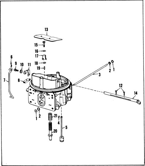
Figure 24. Disassembly-Main Body 4160 With
Mechanical Secondarys |
|
|
|
20 |
| |
Idle By-Pass Adjusting Screw | |
| |
|
|
|
21 |
| |
Idle By-Pass Adjusting Screw Spring | |
| |
|
|
|
|
|
|
| |
|
|
|
|
|
|
|
|
|
|
|
|
| |
|
|
|
|
- 34 - |
|
|
|
|
|
|