| |
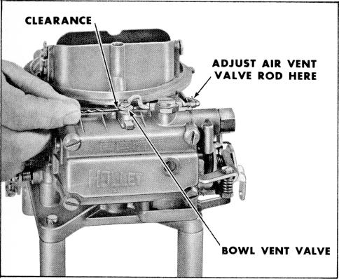
On later models, bend the rod as indicated in
figure 37. After bending the vent rod in either case,
recheck the pump override spring adjustment. |
|
|
 |
| |
|
|
|
|
|
|
|
|
|
| |
 |
|
|
| |
|
|
|
|
|
|
|
|
|
| |
|
|
|
|
|
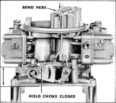
Figure 39. Checking Choke Lever Position |
|
|
| |
|
|
|
|
|
|
|
|
|
| |
|
|
|
|
|
|
|
|
|
|
|
|
|
|
|
|
| |
|
|
Figure 37. Adjusting Air Vent Rod and Valve |
|
|
|
|
|
|
K. CHOKE LEVER CLEARANCE |
|
|
|
| |
|
|
|
|
|
|
|
|
|
|
|
|
|
|
|
|
 |
|
|
|
|
|
|
|
|
| |
(1) On model 4160 with mechanical sec
ondarys, check the choke lever for correct position
by holding the choke closed with the choke lever.
The distance from the center line of the choke
lever hole to the base of the throttle body should
be 1 13/16 inches. If necessary to correct this
distance, bend the choke rod at the location
indicated in Figure 39. This is necessary only
on models with a divorced choke. |
| |
|
|
|
|
|
|
|
| |
|
 |
|
| |
|
|
|
|
|
|
|
|
|
|
|
| |
|
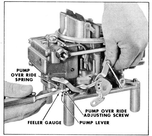
Figure 38. Checking Over Ride Spring Adjustment |
|
|
|
|
|
| |
|
|
|
|
|
|
|
|
|
|
|
| |
|
|
J. CHECKING OVERRIDE SPRING ADJUST |
|
|
|
|
| |
|
|
|
|
|
|
|
|
|
|
|
| |
|
|
|
MENT |
|
|
|
|
|
|
|
| |
|
|
|
|
|
|
|
|
|
|
|
| |
(1) The pump over ride spring adjustment
is checked while holding the throttle in the wide
open position and the pump operating lever held
in a fully compressed position. The clearance
between the adjusting nut and arm of the pump
lever should be .015. |
|
|
|
|
| |
|
|
|
|
|
|
|
|
|
| |
|
|
|
|
|
|
|
|
|
|
|
|
|
|
|
|
| |
(2) After making this adjustment, move
the throttle lever from a closed position toward
open. Any movement at the throttle lever should
be noticed at the pump operating lever. This
indicates correct tip-in. |
|
|
|
|
|
|
|
|
|
| |
|
|
|
|
|
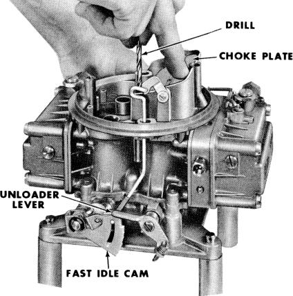
Figure 40. Checking Unloader Adjustment |
|
|
| |
|
|
|
|
|
|
|
|
|
| |
|
|
|
|
L. CHOKE UNLOADER ADJUSTMENT |
|
|