celerator pedal linkage. A clamp screw in the choke lever swivel provides a secure connection to the hand operated choke wire. The adjustable throttle kicker, actuated by a cam on the choke lever, increases the idling rpm during choking to prevent stalling. Two holes in the pump operating lever on the throttle shaft permit adjustment of the accelerating pump discharge for climatic conditions.
B. OPERATION
1. FLOAT SYSTEM
A regulated flow of fuel under pressure from the fuel pump enters the carburetor through the fuel inlet valve. The twin floats rise and fall with the fuel level in the float chamber. The lever connecting the floats controls the fuel inlet needle valve to permit only enough fuel to enter the float chamber to replace that being used. A tab on the float lever limits the downward travel of the floats, preventing them from dropping low enough to bind or stick in the bottom of the float chamber. A passage from the carburetor air inlet vents the float chamber to provide balanced operating pressures within the carburetor. This passage, which is not shown in the illustration, leads into the cavity between the venturi casting and the upper body. A hole in the upper body connects this cavity with the float chamber.
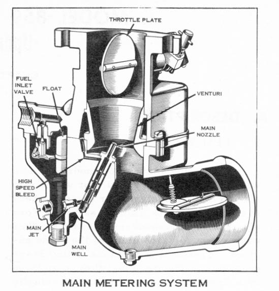
and enters the fuel stream through holes in the side of the main nozzle. The emulsion of fuel and air is discharged into the airstream in the venturi. The high speed bleed is designed to introduce a properly increasing amount of air to the fuel at higher speeds, stabilizing the fuel discharge and counteracting any tendency toward a richer mixture. The emulsion of fuel and air also vaporizes more readily than the raw fuel when it is discharged. The throttle plate controls the amount of the fuel-air mixture admitted to the intake manifold, regulating the speed and power output of the engine in direct accordance with accelerator pedal movement.
2. MAIN METERING SYSTEM
The airflow through the carburetor at normal cruising speeds causes a drop in pressure in the venturi. The air pressure in the float chamber is greater than the reduced pressure at the tip of the main nozzle, which is located in the venturi. This pressure difference forces fuel through the main metering system. The flow of fuel is metered by the main jet and then passes from the main well into the main nozzle. Air from the cavity between the venturi and the upper body passes through the high speed bleed
3. IDLE SYSTEM
a. At idle and low speeds, the pressure drop in the venturi is not sufficient to operate the main metering system. The high manifold vacuum in this speed range is used to provide a pressure difference which will operate the idle system. The pressure of the air in the float chamber forces fuel through the main jet into the main well. The fuel rises inside the main nozzle, passes through calibrated holes in the lower por-