Remove the idle adjusting needle (15) and spring (16). Discard the needle.
Slide the venturi (13) out of the upper body casting.
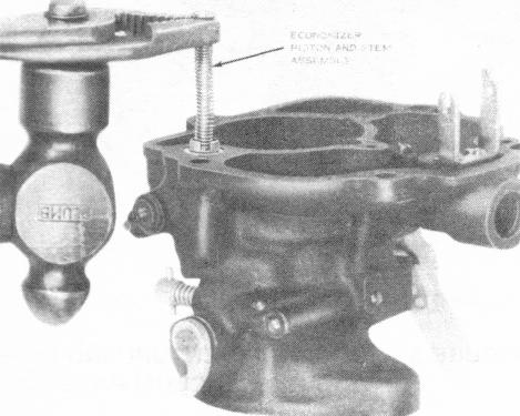
Grasp the economizer piston and stem assembly (14) at the end with a pair of pliers and pull the assembly out of the casting. Discard this assembly.
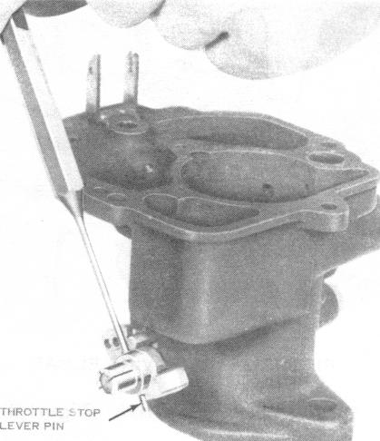
FIGURE 7 - REMOVING THROTTLE STOP LEVER PIN
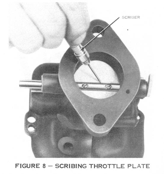
edges of the throttle shaft for proper alignment during r,-assembly. Remove and discard the two throttle plate screws (25). Slide the throttle plate (26) out of the shaft.
Loosen the throttle lever clamp screw (17) and remove the throttle lever (18).
Remove the pump link retainer (19) and slide the pump link (20) out of the pump operating lever. Discard these parts.
Remove the throttle stop screw (21) and spring (22).
Drive out the pin (23) in the throttle stop lever with a punch having a diameter no larger than 332". Remove the lever (24) from the throttle shaft.
Scribe lines on the upper surface of the throttle plate along both
(7) (8) (9) (10)
(11) (12)