| |
|
|
|
9D-3
MODELS 2G-2GC-2GV
PAGE 5
|
| |
|
|
|
|
|
|
consists of a spring, bronze or paper filter, relief spring, and a gasket. The open end of the bronze filter faces the fuel inlet nut as shown in Figure 1. The "Vee" shaped inpression increases the filtering area. The bronze and paper filter elements are spring-loaded to provide a pressure relief so that in the event the filter should clog, the restriction will cause fuel pump pressure to overcome the filter relief spring pressure and allow fuel to by-pass the filter, to keep the engine running and enable the driver to get to a service outlet for filter replacement.
|
|
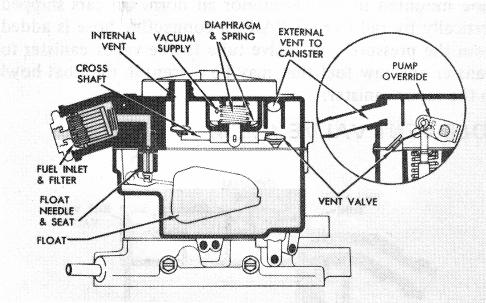
FLOAT SYSTEM - VACUUM OPERATED VENT VALVE (Fig. 2)
|
| |
 |
|
There are several methods of float bowl venting used in the Model "G" 2-bore carburetor. The method and type of venting used for a particular engine will be varied in design to meet the flow characteristics desired for the engine on which it is used.
|
|
|
Some applications use a "fixed" external vent located on top of the carburetor air horn just above the float bowl chamber. This vents to the outside any fuel vapors which may form in the fuel bowl due to engine heat during periods of hot engine operation. This keeps the vapors from being forced into the carburetor bores thereby causing poor idle and hard hot starting due to excessive richness.
|
|
|
| |
|
FIGURE 2
|
|
|
| |
To meet California emission requirements for evaporative losses, the float bowl on some California 2GV models is internally vented by a vacuum operated vent system.
|
| |
The vent system assures that any pressure "build-up" in the float chamber during hot engine operation, caused by fuel vapors, will be relieved through a vent hole leading to a vapor collection canister.
|
An internal vent located inside the air horn bore just beneath the air cleaner, is used to help balance the pressure from beneath the air cleaner to the fuel in the float bowl. The amount of fuel metered by the carburetor is dependent upon the pressure in the float bowl causing fuel to flow. By locating vents internally below the air cleaner, the carburetor automatically compensates for built-in air cleaner restriction; hence, a balance can be maintained between the air flowing through the carburetor venturi and the air acting upon the fuel in the float bowl. If the carburetor is also equipped with a fixed external vent, it will not be com,)letely balanced but the pressure difference will be less, so consequently, the internal vent tube will very much efff.;t carburetor calibration. Fuel vapors will also be drawn from the area above the fuel in the float bowl by the internal vent during engine operation and is compensated for in the calibration of the carburetor unit.
|
|
| |
During normal operation when the engine is running, manifold vacuum that leads from the channel in the air horn to the top side of a small diaphragm mounted inside the air horn, pulls the diaphragm upward against spring tension, closing off a valve on the channel which leads to the vapor canister. This gives complete internal venting while the engine is running. When the engine is shut down and no vacuum is applied to the vent valve diaphragm, the spring pressure pushes downward on the diaphragm, closing off the internal vent and opening the vent hole leading to the vapor canister.
|
| |
A tang on the pump arm mechanically closes the vent hole to the vapor canister at higher speeds should the manifold vacuum drop to the point where the vent hole to the canister might be open and destroy the internal carburetor balance.
|
The float system, on some models, has an atmospheric idle vent valve which is normally open only during the engine idling period and when it is shut down. The idle vent valve is used in place of the fixed external bowl vent and is operated by a tang on the pump lever. When the throttle lever is in the idle speed position, the idle vent valve is open to allow any fuel vapors in the float bowl during periods of hot engine idle and hot soak to be vented to the outside. The vent valve closes when the throttle valves are opened to the off-idle position at which point the carburetor returns to an internal balance by the internal vent tube which transmits air pressure from beneath the air cleaner to the fuel in the float bowl.
|
|
| |
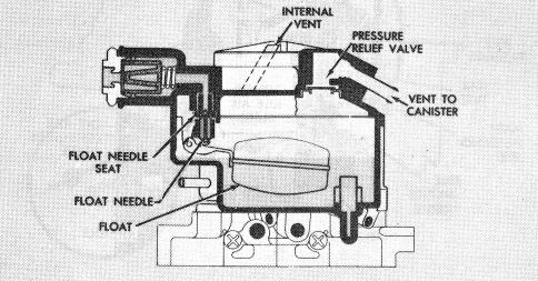
FLOAT SYSTEM - PRESSURE RELIEF VALVE (Fig. 3)
|
| |
 |
|
It is necessary that the idle vent valve be closed during all periods of operation except at idle; otherwise excessive richness can be caused by the higher atmospheric pressure acting upon the fuel in the float bowl.
|
|
|
| |
|
|
|
|
|
| |
|
FIGURE 3
|
|
|