| |
|
|
|
|
|
|
|
|
|
|
|
|
|
| |
|
|
|
|
|
|
|
|
|
|
|
|
|
The compensator valve is operated by a bi-metal strip that senses temperature. At a certain predetermined temperature, when extra air is needed to off-set the enriching effects of fuel vapors, the bi-metal strips bends and unseats a valve which uncovers the air channel leading from the carburetor venturi to below the throttle valves. At this time, just enough air is added to the engine to offset the richer mixtures and maintain a smooth engine idle. When the engine cools and the extra air is not needed, the bi-metal strip closes the valve and operation returns to normal mixtures. Hot idle compensators are pre-set at the factory and require no adjustment. However, to insure proper idle adjustment, the valve must be closed when setting engine idle speed and mixtures. This can be done by using a screwdriver to press down lightly on the valve for those models with the valve located in the main venturi area (left picture). On those models with the valve located at the rear of the float bowl (right picture), hold spring-loaded button "in" when making the idle settings. If no button is available, remove idle compensator cover and using a screwdriver, press in lightly on the valve when making idle settings. Replace cover after completing idle adjustments.
|
|
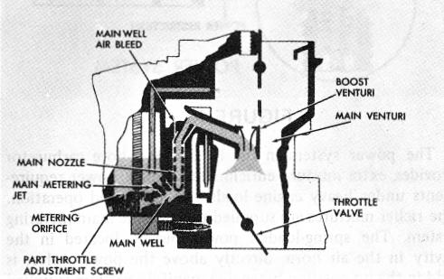
With the increased throttle opening, there is an increased air velocity in the venturi system. This causes a drop in pressure in the main venturi which is increased many times in the boost venturi. Since the low pressure (high vacuum) is now in the boost venturi, fuel will flow in the following manner:
|
| |
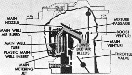
The low pressure in the boost venturi is transmitted to the tip of the main well tube or main discharge nozzle. Atmospheric pressure, which is greater, forces fuel from the float bowl through the main metering jets and into the main well. As the fuel passes through the main well tubes, it is mixed with air from the calibrated main well bleeds. The fuel mixture then passes from the tip of the discharge nozzle, through the mixture passage, to the boost venturi and on into the intake manifold.
|
| |
As the throttle valve opening is increased and more fuel is drawn through the main well tubes, the fuel in the main well drops. The calibrated holes in the main well tubes are proportionately exposed to the air in the upper well area. When this occurs, they become air bleeds mixing progressively more air with the fuel passing through the main well tubes. Therefore, although the nozzle suction is increased at higher engine speeds, the air/fuel mixture to the engine remains constant throughout the part throttle range.
|
| |
|
|
|
|
|
|
|
MAIN METERING SYSTEM
|
|
|
|
|
|
| |
|
|
|
|
|
|
|
MAIN METERING SYSTEM (Fig. 10)
|
|
|
|
|
ADJUSTABLE PART THROTTLE (See Figure 10)
|
| |
|
|
|
|
|
|
|
 |
|
|
Some exhaust emission control carburetors use the adjustable part throttle (A.P.T.) feature. The A.P.T. consists of a tapered metering screw located in a channel on the bottom of the float bowl. This channel supplements and controls fuel to the main metering system to maintain a very close tolerance of fuel mixtures during part throttle operation. The A.P.T. screw is set at the factory and sealed. No attempt should be made to adjust the metering screw in the field.
|
| |
|
|
|
|
|
|
|
| |
|
MAIN WELL INSERTS (Fig. 11)
|
|
|
| |
|
|
|
|
|
|
|
| |
|
|
 |
|
| |
FIGURE 10
|
|
|
|
|
|
|
|
|
| |
|
|
|
|
|
|
|
|
|
The main metering system supplies fuel to the engine from off-idle to wide open throttle. Such factors as rear axle ratio, vehicle weight, engine and transmission design vary the speed at which main metering mixtures are required. The main metering system provides efficient fuel metering during the cruising range of the vehicle. Its operation is dependent upon air flow through the carburetor venturi which, in turn, creates a low pressure in the venturi area causing fuel to flow.
|
|
|
|
| |
|
|
|
|
|
|
| |
|
|
FIGURE 11
|
|
|
|
As the throttle valves are opened beyond the off-idle discharge holes or slot, allowing more air to enter the intake manifold and engine speed to increase, the vacuum decreases below the throttle valves so the air/fuel mixture below the throttle valves from the off-idle gradually diminishes.
|
|
|
|
|
|
|
| |
|
|
|
|
|
|
| |
In some 2-bore carburetor applications, main well inserts are used. They are larger than the main well tubes and set in a recess beneath the venturi cluster. The main well inserts surround the main well tubes and have calibrated holes which are similar to those in the main well tubes. The
|