9D-3
|
|
|
|
|
|
|
|
|
|
|
|
|
|
MODELS 2G-2GC-2GV PAGE 12
|
|
|
|
|
|
|
|
|
|
|
|
|
| |
|
|
|
|
|
|
|
|
|
|
|
|
|
|
| |
|
|
|
|
|
|
|
|
|
|
|
|
|
|
causing a momentary leanness. The accelerator pump is used to provide the fuel necessary for smooth operation during this time.
|
|
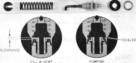
Some models use a synthetic "floating" pump cup which uses no vapor vent ball. The up and down movement of the "floating" cup on the pump head either "seats" to provide a solid charge of fuel on the down-stroke or "unseats" on the up-stroke to allow fuel to flow by the cup and fill the pump well. The cup remains unseated when there is no pump plunger movement to vent vapors in the pump well.
|
Fuel for acceleration is supplied by a double springloaded pump plunger operated by a pump shaft and lever assembly, in the air horn, connected directly to the throttle lever by a pump rod. The top and bottom springs combine to move the plunger so that a smooth sustained charge of fuel is delivered for acceleration.
|
|
| |
Some applications use a pump cup expander (Garter) spring to maintain constant pump cup to pump wall contact. This feature may be included in the original equipment carburetor or may be added in field replacement (known as a Heavy Duty pump) on some applications.
|
,When the pump plunger moves upward as happens during throttle closing, fuel enters the slotted pump well, flows by the check ball in the plunger head and also around the side of the pump plunger and into the bottom of the pump well.
|
|
| |
|
|
|
|
|
|
| |
CHOKE SYSTEMS
|
|
|
|
| |
|
|
|
|
|
|
On some model 2-bore carburetors, a fuel inlet check ball and channel is used in the bottom of the pump well. In this type unit, fuel is drawn from the channel through an inlet screen in the bottom of the float bowl.
|
|
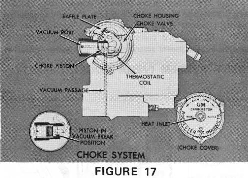
MODEL 2GC CHOKE SYSTEM (Fig. 17)
|
|
|
| |
|
|
|
|
|
|
| |
 |
|
When the throttle valves are opened, the connecting linkage forces the pump plunger downward in the well. The downward motion of the plunger seats the check ball in the plunger head. Fuel is forced through the pump discharge passage where it unseats the pump discharge check ball and passes on through the passage to the pump jets in the cluster where it sprays into the venturi area.
|
|
|
The check ball in the pump plunger head (see inset) also serves as a vapor vent from the pump well. When the pump plunger is not in operation, the check ball drops off its seat and vents any vapors which may form in the bottom of the pump well into the float bowl area. Without this vapor vent check ball, vapor pressure in the pump well might force fuel from the pump system into the engine manifold causing hard starting and pump slugging conditions under extreme heat. The vapor vent check ball in the pump plunger head also allows any vapors in the bottom of the pump well to escape so that a solid stream of fuel may be maintained from the pump plunger at all times.
|
|
|
| |
|
|
|
|
|
|
| |
The conventional Model 2GC choke system may have the choke housing assembly mounted on the air horn or throttle body. On units with the housing on the throttle body, an intermediate choke rod adjustment is necessary. The principles of operation are the same on both units.
|
The pump discharge check ball is used in the pump discharge passage to prevent air from being drawn into the passage during upward movement of the pump plunger to prevent a momentary delay in delivery of fuel.
|
|
The choke system consists of a thermostatic coil assembly, choke piston, offset choke valve and fast idle cam and linkage. Its operation is controlled by a combination of intake manifold vacuum, the offset choke valve, and temperature.
|
"FLOATING" PUMP CUP (Fig. 16)
|
|
|
|
|
| |
|
|
|
When the engine is cold, the thermostatic coil is calibrated to hold the choke valve closed. As the engine is started, air velocity against the offset choke valve causes it to open slightly against the torque of the thermostatic coil. In addition, intake manifold vacuum is applied to the choke piston through a passage which also tends to open the choke valve. The choke valve assumes a position where the torque of the thermostatic coil is balanced against vacuum pull on the choke piston and air velocity against the offset choke valve. This is when the choke piston is in the vacuum break position (See inset). This results in a regulated air flow into the carburetor which provides the richer mixture needed during the warm-up period.
|
| |
|
|
|
|
|
|
|
|
| |
 |
|
|
| |
|
|
|
|
|
|
|
|
| |
|
|
FIGURE 16
|
|
|
|
|
|