9D-3
|
|
|
|
|
|
|
|
|
|
|
|
|
|
|
|
|
|
|
|
|
MODELS 2G-2GC-2GV PAGE 24
|
|
|
|
|
|
|
|
|
|
|
|
|
|
|
|
|
| |
|
|
|
|
ASSEMBLY OF THROTTLE BODY - ALL MODELS (Figure 39)
|
|
|
|
|
|
|
|
|
| |
|
|
|
|
|
|
|
|
|
|
|
|
|
|
|
|
|
|
|
| |
|
|
|
|
|
|
|
|
|
|
|
|
|
|
|
|
|
|
|
|
|
|
| |
|
|
|
|
|
|
|
|
|
|
|
|
|
|
|
it seats. Then back out (3) full turns as a preliminary idle adjustment.
|
As mentioned during throttle body disassembly, there is a very close tolerance fit between the throttle valves and bores. Also the idle discharge orifices are drilled or punched in relation to a proper fitting valve. Therefore, if the throttle valves, levers or shaft are worn excessively or damaged, a complete throttle body assembly is required.
|
|
|
4. Install main well insert tubes (if used) into main well. Make sure they are seated in recess provided.
|
| |
|
5. Drop steel pump discharge ball into pump discharge cavity. Ball is 3/16" diameter steel. Install pump discharge spring and T-shaped retainer.
|
| |
|
|
|
NOTE: The top of retainer should be flush with
|
|
| |
|
|
NOTE: Refer to the carburetor part number
|
|
|
|
|
|
|
top of float bowl casting beneath venturi
|
|
| |
|
|
stamped on the tag or bowl; then consult the
|
|
|
|
|
|
|
cluster.
|
|
|
|
|
|
| |
|
|
Delco 9C Parts Bulletin for a listing of parts
|
|
|
|
|
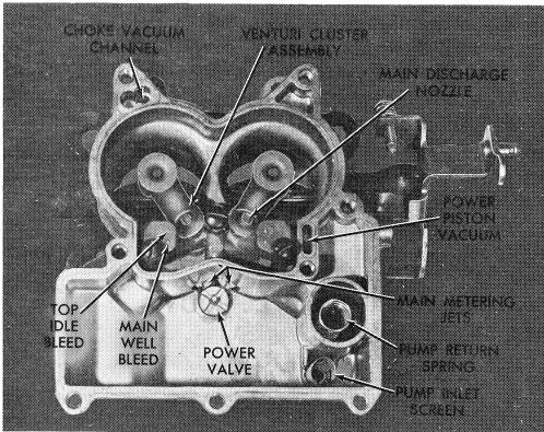
6. Install gasket and venturi cluster assembly. Install center screw (with smooth shank) using a fibre gasket in place of a lockwasher for sealing the pump discharge passage. Install remaining (2) cluster screws and lockwashers. Tighten the (3) cluster screws evenly and securely.
|
| |
|
|
used.
|
|
|
|
|
|
|
|
|
|
|
|
| |
1. If removed, install the idle mixture adjusting needles and springs in the throttle body until finger tight. Then, back out needles specified number of turns as a preliminary idle adjustment. (See step 14, page 21, Throttle Body Disassembly.)
|
|
|
| |
|
|
|
|
NOTE: On some models, a high-speed baffle is
|
|
| |
|
|
CAUTION: Do not force the idle mixture needles against the seat or damage will result.
|
|
|
|
|
|
|
used. Install the baffle under the center cluster
|
|
| |
|
|
|
|
|
|
|
|
screw with a fibre gasket on each side of the
|
|
| |
2. If removed, install the slow and fast idle screws in
|
|
|
|
|
baffle. The notches on the high-speed baffle
|
|
| |
|
throttle levers.
|
|
|
|
|
|
|
|
|
|
|
|
|
point downward towards the venturi area.
|
|
|
| |
|
|
NOTE: If the choke housing is throttle body mounted, the installation is covered under FINAL CARBURETOR ASSEMBLY.
|
|
|
|
|
7. If used, install the hot idle compensator gasket and assembly. Tighten screws evenly and securely. Install compensator cover if mounted on rear of float bowl.
|
|
|
|
|
|
|
|
|
|
|
|
|
|
|
|
8. Install power valve (power enrichment valve - Vega) and gasket in bottom of float bowl using tool BT-3007. Tighten securely.
|
ASSEMBLY OF FLOAT BOWL (Fig. 40)
|
|
|
|
|
|
 |
|
|
| |
|
9. Install (2) main metering jets. Tighten securely. After tightening, check to be sure there are no burrs on face of jet at fuel inlet orifice.
|
| |
10. If bowl has pump inlet passage, install small aluminum inlet check ball in bottom of pump well. Install pump return spring into pump well applying pressure with finger to center it in pump well. Make sure spring is seated in bottom of well.
|
| |
11. Install pump inlet screen in bottom of float bowl (where used).
|
| |
|
|
|
NOTE: Refer to the Delco 9C Parts Bulletin for
|
|
| |
|
|
|
use of pump inlet check ball and screen for use
|
|
| |
|
|
|
on a particular application.
|
|
|
|
|
| |
12. At this point, it is suggested the accelerator pump system be checked for sufficient pump fuel delivery. Fill the pump well with fuel; insert the pump plunger assembly in the well and force the pump assembly up and down in the well several times observing that a solid steady stream of fuel is discharge into the venturi bores from each of the pump jets. Remove pump from well after test.
|
| |
|
|
|
|
|
|
|
|
|
|
|
|
|
| |
|
|
|
|
|
FIGURE 40
|
|
|
|
|
|
|
| |
|
|
|
|
|
|
|
|
|
|
|
|
|
ASSEMBLY OF FLOAT BOWL - (Figure 40)
|
|
|
|
|
|
13. If used, install metal dam in slot in fuel reservoir along side pump well.
|
| |
1. Invert the float bowl and place new throttle body gasket in position over locating dowels making sure gasket holes line up with holes in float bowl. Then, install throttle body on bowl using (3) attaching screws and lockwashers. Tighten evenly and securely.
|
|
| |
|
|
|
|
|
|
|
|
|
|
| |
|
ASSEMBLY OF AIR HORN - (Figure 41)
|
|
|
|
| |
|
|
1. On 2G models, install torsion spring and choke lever and swivel assembly on air horn. Install retaining annular ring in groove.
|
| |
2. Install distributor vacuum fitting into float bowl, if removed.
|
|
|
| |
|
|
2. On 2GC models, install choke housing gasket and housing to air horn, retaining with (2) attaching screws. Tighten evenly and securely.
|
| |
3. Install idle air by-pass adjustment screw (where used) into rear of float bowl. Turn screw inward lightly until
|
|
|