| |
|
|
|
|
|
|
|
|
|
|
|
|
9D-3
MODELS 2G-2GC-2GV
PAGE 27
|
|
|
| |
|
|
|
|
|
|
|
|
|
|
|
|
|
|
|
|
|
|
|
| |
|
valve is just closed and index marks are aligned as described in the 9D-3 Section of the Delco Parts and Service Manual (9X).
|
|
ASSEMBLY OF SPLIT CHOKE LINKAGE (Fig. 45)
|
|
|
|
| |
|
|
|
 |
|
|
| |
|
Tighten stat cover screws after adjustment.
|
|
|
|
|
|
|
| |
|
|
|
|
|
|
|
|
|
|
ASSEMBLY OF CHOKE (PISTON TYPE) MOUNTED ON THROTTLE BODY (Fig. 44)
|
|
|
|
|
|
| |
 |
|
|
|
|
| |
|
|
|
|
|
|
|
|
|
|
|
|
|
| |
|
|
|
|
FIGURE 45
|
|
|
|
|
|
|
| |
|
|
|
|
|
|
|
|
|
|
|
|
|
| |
|
|
3. Install fast idle cam to throttle body, retaining with fast idle cam screw. Tighten securely.
|
|
| |
|
|
|
|
|
|
|
|
|
|
|
|
|
| |
|
|
|
|
|
|
|
2GC CHOKE HOUSING GASKET (Fig. 46)
|
|
|
|
| |
|
|
FIGURE 44
|
|
|
|
|
 |
| |
|
|
|
|
|
|
|
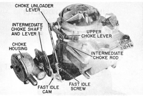
ASSEMBLY OF CHOKE (PISTON TYPE) MOUNTED ON THROTTLE BODY - (Figure 44)
|
|
| |
1. Install intermediate choke shaft and lever into choke housing. Lever on shaft should hang downward between mounting bosses.
|
|
| |
2. Install new gasket, then install choke housing on throttle body using (2) attaching screws. Tighten securely.
|
|
| |
3. Assemble choke piston to choke piston link and lever assembly with piston pin. Then install choke piston and lever assembly into choke housing. Attach choke piston lever to end of intermediate choke shaft with retaining screw. (Make sure flats in lever hole line up with flats on intermediate choke shaft.) Tighten retaining screw securely.
|
|
| |
4. Install intermediate choke rod to upper choke lever and intermediate choke lever, retaining with clips provided. Adjust choke piston as outlined under Intermediate Choke Rod Adjustment in 9D-3 Section of Parts and Service Manual (9X).
|
|
| |
|
|
|
|
|
FIGURE 46
|
|
|
|
|
|
| |
|
|
|
|
|
|
|
|
|
|
|
|
|
| |
5. Install baffle plate inside choke housing, then install stat cover and coil assembly using new gasket.
|
|
|
|
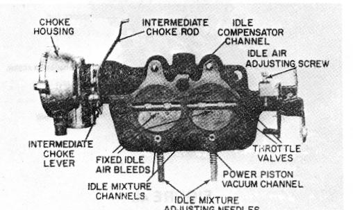
ASSEMBLY OF CHOKE (2GC WITH VACUUM BREAK UNIT) MOUNTED ON THROTTLE BODY - (Figure 46)
|
|
| |
|
Adjust thermostatic coil as outlined in 9D-3 Section of Parts and Service Manual. Install (3) cover screws and retainers. Tighten securely.
|
|
|
|
|
| |
|
|
|
|
|
|
|
|
|
|
|
|
|
|
| |
|
|
|
4. If removed, install the fast idle lever on the end of the throttle shaft with attaching screw. Tighten securely. Install the fast idle speed screw and spring into fast idle lever.
|
|
| |
|
|
|
|
|
|
|
|
|
ASSEMBLY OF SPLIT CHOKE LINKAGE-- (Figure 45) 1. Assemble choke housing to throttle body as described previously.
|
|
|
|
| |
2. Assemble flat washer on intermediate choke lever end of choke rod, then insert end of choke rod into the intermediate lever and fast idle cam, as shown. Retain with clips.
|
|
|
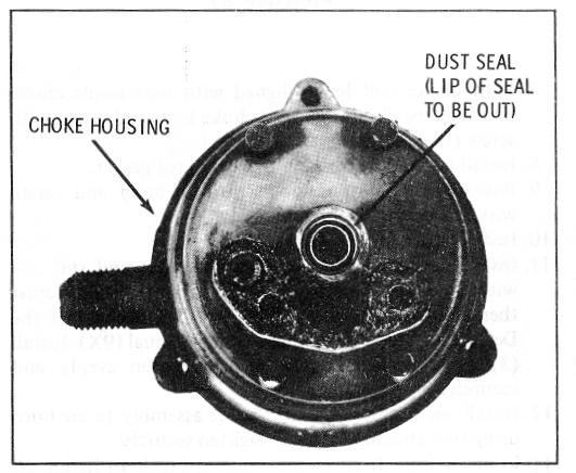
5. Install new dust seal in the choke housing. Lip goes toward carburetor when housing is installed on throttle body.
|
|
| |
|
|
6. Install choke coil lever into choke housing.
|
|
|
|
|