Bulletin 9D-8 August, 1951 Model "BC" Page 4
IDLE SYSTEM
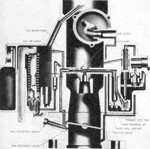
The Idle System controls and delivers the proper fuel/air mixture for idling and up to approximately 30 MPH.
As shown on Figure 2, the idle fuel first passes from the bowl through the calibrated Main Metering Jet attached to the bottom of the Main Well Assembly. This fuel is then drawn up the Main Well by manifold vacuum (suction) to the crossbar in the Air Horn. Air joins the fuel through the calibrated air bleeds in the center of the crossbar. This fuel/air mixture is then calibrated as it passes through the Idle Restriction and is drawn down the passage in the Float Bowl to the Throttle Body.
The idle fuel is then metered to the engine by the idle adjusting needle hole which is below the throttle valve. As the throttle valve is opened to a greater degree, the idle hole which was above the closed throttle valve, is exposed to manifold vacuum and delivers additional fuel to meet the increased engine demand.
PART THROTTLE SYSTEM
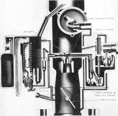
As the throttle valve is opened further, (as shown in Figure 3), air at a higher velocity is drawn down the carburetor throat. This creates a pressure drop or suction in the venturi at the main discharge nozzle in the crossbar. As a consequence, fuel and air begin to pass from the main nozzle to meet the increased engine demand. Further throttle opening will result in greater air velocity passing through the carburetor with resultant higher fuel flow from the nozzle and decreased flow from the idle system until it eventually cuts out altogether.
The calibration of the Main Metering Jet and the Air Bleeds in the crossbar maintain economical fuel/air ratios throughout the part-throttle or cruising range.
Figure 2. Idle System
Figure 3. Part Throttle System