| 13 of 76 |  |
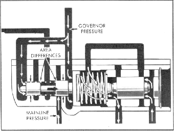
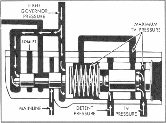
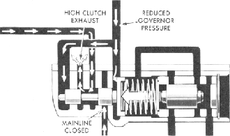
Fig. 19PG-Low Drive Valve Snap Action
As the vehicle reaches the minimum throttle shift point
(refer to shift chart), governor pressure moves the shift valve
to the right with the valve stem causing the regulator valve to
block TV pressure flow through the by-pass (fig. 18PG). As
the regulator valve continues to the right, it opens an exhaust
for the TV pressure in the area between the shift valve and the
regulator valve.
This sudden release of pressure allows the shift valve to
snap to the right and open mainline pressure to the high-clutch
apply passage. This snap action of the low-drive shift valve is
helped by the mainline pressure acting on the difference in
area between spools 1 and 2 of the shift valve (fig. 19PG). The
overall design of the shift and regulator valves eliminate any
"hunt", that is, moving back and forth when the transmission
is at a shifting point.
Medium-Throttle: To-Detent shifts are all controlled in the
manner just described, however, the TV pressure is regulated
at higher pressures (fig. 18PG). As the TV pressure increases,
the shift point occurs at higher road speeds.
Through-Detent upshifts occur when the TV plunger
causes full TV pressure to develop and also forces the detent
valve into its bore. With the detent valve bottomed, the regu
lator valve exhaust port is blocked, and TV pressure is trans
ferred in the area between the detent spools. This TV pressure
enters the detent passage and supplies TV pressure to the
spring side of the shift valve after the regulator valve closes the
by-pass (fig. 20PG). In this way, the "through-de tent upshift"
is delayed to the highest possible road speed. At this speed,
governor pressure snaps the shift valve to the right and accom
plishes the shift to high range.
Automatic Downshifts
Automatic Downshifts to low range are divided into three
types: Coast Downshift, To-Detent, and Through-Detent
forced downshifts. The control for these downshifts is pro
vided by pressure differentials acting on the low-drive shift
valve, and the regulator valve. These pressures (governor,
throttle valve, and detent) are the same ones that created the
upshift condition previously discussed. In the case of the vari
ous downshift conditions, the low-drive shift valve is moved to
the left, closing the mainline to high clutch apply passage. The
conditions that cause these shifts are; reduced road speed,
increased pressure on the accelerator, or a combination of
both.
NOTE: The shift point speeds, shown for reference in this
discussion, pertain to the Chevrolet 327 cubic inch V8
engine. Refer the chart for complete shift point listings.
Coast Downshift. As the vehicle slows down, governor
pressure (holding the low-drive shift valve to the right) is
reduced. At approximately 18 to 14 m.p.h., governor pressure
is less than the opposing spring force of the shift valve springs.
When this occurs, the springs snap the valve to the left,
shutting off mainline pressure and opening the high-clutch
apply oil to exhaust (fig. 21PG).
To provide a smooth downshift when the high-clutch
apply pressure is exhausted, servo release pressure returning to
exhaust is metered through two small openings located beside
the check ball of the downshift timing valve. As a result of this
metered restriction in the servo-release path to exhaust, appli
cation of the low band is slightly delayed. This delay allows
Fig. 20PG-Through Detent Upshift
Fig. 21 PG-Coast or Part Throttle Downshift