| 27 of 76 |  |
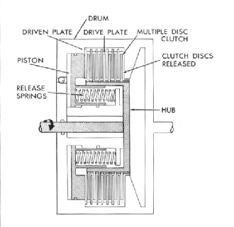
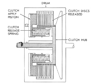
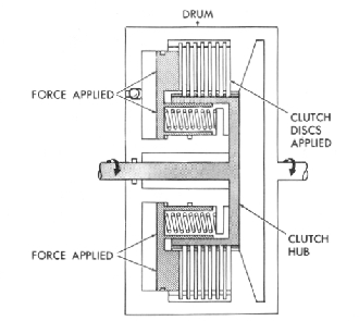
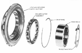
Fig. 6M-Multiple Disc Clutch
(applied in all forward speeds) drives the input (front) ring
gear clockwise. The ring gear drives the pinions clockwise on
their shafts causing the sun gear to turn counterclockwise and
the carrier (output shaft) to turn clockwise since both gear sets
have a common sun gear with two sets of teeth, the input to
the rear gear set is through the sun gear turning counterclock
wise. The rear gear set pinions are forced to turn clockwise
because the carrier is prevented from turning counterclockwise
by the low roller clutch. The pinions react against the carrier
to turn the output (rear) ring gear clockwise and drive the
vehicle.
To achieve minimum reduction, the intermediate clutch
Fig. 8M-Clutch Released
applies the intermediate roller clutch preventing the sun gear
from turning counterclockwise. Drive reactions are loading the
sun gear counterclockwise, therefore the sun gear is stopped in
second gear.
The forward (input) ring gear turning clockwise, causes the
pinions to rotate clockwise on their shafts and allows the
carrier and output shaft to rotate clockwise.
Direct drive is obtained by applying the direct clutch,
locking the sun gear to the input shaft. With the forward
clutch locking the forward ring gear to the input shaft, two
members of the planetary gear set are locked together placing
the transmission in direct drive.
Reverse drive is obtained by applying the direct clutch
driving the sun gear through the sun gear driving shell. The
front gear set is not used in reverse. With the input to the sun
gear on the rear gear set and the rear carrier stationary, the
pinions turn counterclockwise on their shaft causing the ring
gear to turn counterclockwise. Since the ring gear is splined to
the output shaft, the vehicle is driven backwards.
Fig. 7M-Clutch Applied
Fig. 9M-Roller Clutch Components