| 37 of 76 |  |
shaft. The governor consists of two sets of flyweights, two
springs and a regulator valve. Centrifugal force of the fly
weights is imposed on the regulator valve, causing it to regulate
a pressure signal that increases with increasing speed.
Centrifugal force is proportional to the square of vehicle
speed. This means that a given change in vehicle speed results
in a smaller change in governor pressure at low speeds than at
high speeds. Because of this characteristic a governor with a
single set of weights has less pressure change at low speed than
at high speed. To increase the pressure change of the governor
signal at low speeds, the flyweights are so designed that their
effective mass is greater at speeds below approximately 720
governor rpm than it is above this speed.
This is done by arranging the primary weights so that they
act through preloaded springs on the secondary weights, which
in turn acts on the valve. At approximately 720 rpm the
centrifugal force on each primary weight exceeds the spring
force and the primary weights move against a stop. With the
primary (larger) weights stopped, the force on the governor
regulator valve is equal to the spring forces plus the centrifugal
force on the secondary (smaller) weights.
In 1971, another version of this governor is used to pro
vide more control of shift schedules. By putting in preloaded
springs of unequal loads, two speeds may be obtained where
the primary weights move against a stop one at a time. This
provides three stages to the governor pressure versus speed
relationship.
The force of the oil supplied to the governor acts to close
the governor valve and this pressure is opposed by the centri
fugal force of the rotating flyweights attempting to open the
valve. As a result, governor valve position is always the balance
point between these two forces and governor pressure is then
proportional to car speed-increasing or decreasing as the car
speed increases or decreases. The governor pressure is regulated
by movement of the governor valve, exhausting a portion of
the oil supplied to it.
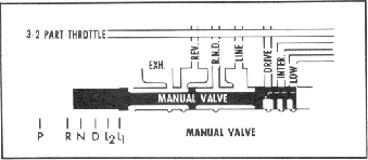
Manual Valve
The manual valve (fig. 21M) establishes the range of trans
mission operation (i.e. P-R-N-D-La-Li) as selected by the
vehicle operator through the manual selector lever.
When the manual valve is in the drive (D) position there
are two outputs; drive oil and reverse-neutral-drive (R-N-D) oil.
R-N-D oil is available in reverse, neutral and drive to insure the
band is held off in drive and prime the direct clutch accumu
lator. Drive oil will now apply the forward clutch and first gear
is achieved. Drive oil is supplied to the governor to be reregu
lated to governor oil pressure. As the vehicle speed increases,
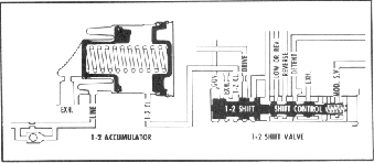
Fig. 22M-1-2 Shift Valve
the force on the right hand end of the valve increases and in
turn governor pressure increases.
1-2 Shift
To accomplish a 1-2 shift, the shift valve (fig. 22M) must
move to the right, opening the intermediate clutch port to
mainline pressure. Governor pressure is pushing the valve to
the right and modulator pressure and the spring are pushing it
to the left. Governor pressure builds to a point where it slowly
starts to move the shift valve and crack open the port to
mainline pressure and close the exhaust port. The shift valve
then has mainline pressure also pushing it to the right and it
snaps over to the second speed position. Intermediate clutch
pressure will now apply the clutch and stroke the intermediate
clutch accumulator piston. When the accumulator piston is
being stroked, the force on the left side is constant. The spring
force acting on the right side, decreases so the oil pressure
must increase during the stroking or clutch apply time. The
clutch pressure therefore starts low and increases to give a
smooth positive shift.
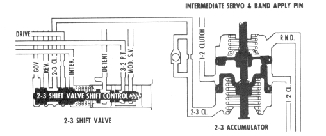
2-3 Shift Valve
The 2-3 upshift is accomplished in the same manner as the
1-2 upshift.
The 2-3 shift valve (fig. 23M) has the following oil pres
sure acting on it; governor pressure on the left end, modulator
pressure on the right end. When the force caused by governor
oil pressure exceeds the force caused by modulator oil plus the
spring forces, the 2-3 shift valve will move to the right closing
the exhaust port and opening the inlet port. The shift valve
now has an additional force (drive oil) snapping it to the right.
Drive oil will then apply the direct clutch to provide high gear.
Accumulator action is also provided for the 2-3 shift by the
direct accumulator in the valve body.
Closed throttle downshifts will not occur until the
Fig. 21M-Manual Valve
Fig. 23M-2-3 Shift Valve