| 6 of 76 |  |
POWERGLIDE
INDEX
PAGE
Theory of Operation .........................
3
Mechanical Components & Powerflow ...........
3
Hydraulic Components ......................
Hydraulic Unit Operation ...................
8
Diagnosis .................................
19
THEORY OF OPERATION
MECHANICAL COMPONENTS AND
POWERFLOW
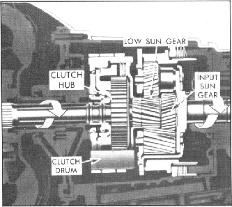
When the selector lever is placed in the (Drive) "D" range,
which is the normal driving range, the transmission is auto
matically shifted into its low range (Fig. 2PG). The clutches
are released and the low band is applied to the outside
diameter of the clutch drum. With the low band applied, the
clutch drum is held stationary which in turn holds the clutch
flange and low sun gear stationary. Drive then is from the
converter pump to the converter turbine and through the
input shaft, to the input sun gear in the planetary gear set. The
input sun gear drives the long pinions which in turn drive the
short pinions. The short pinions are in mesh with the low sun
gear. Since the low sun gear is held stationary with the low
band applied, the short pinions will walk around the low sun
gear, and as they walk around the sun gear they carry the
planet carrier and the output shaft to which they are attached,
with them at a reduction of 1.82 to 1 or 1.76 to 1 depending
on engine application.
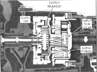
The transmission will automatically upshift to the high
range (Fig. 3PG) or direct drive at between 10 and 68 mph
depending on the particular vehicle and on throttle position.
When this shift occurs, the low band is released and the high
clutch is applied which locks the planetary system causing it to
rotate as a unit. This is accomplished in the following manner:
With the clutch applied, the clutch hub which is splined to the
input shaft is locked to the clutch flange and low sun gear
through the medium of the clutch plates. The low sun gear is
Fig. 3PG-Powerflow in High Gear
meshed to the short pinions, the short pinions are meshed with
the long pinions and the long pinions are meshed with the
input sun gear which is also splined to the input shaft. Since
both the low sun gear and the input sun gear are now locked
to the input shaft, the entire planetary unit will revolve at
input shaft speed, direct drive 1 to 1 ratio.
Fig. 2PG-Powerf low in Low Gear
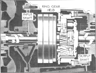
Fig. 4PG-Powerflow in Reverse Gear