|
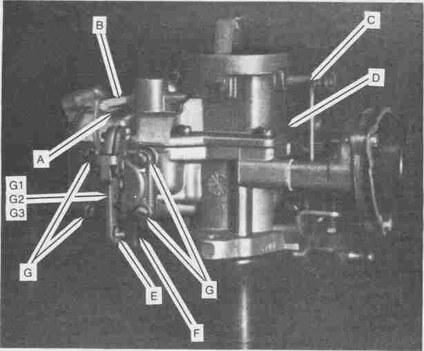
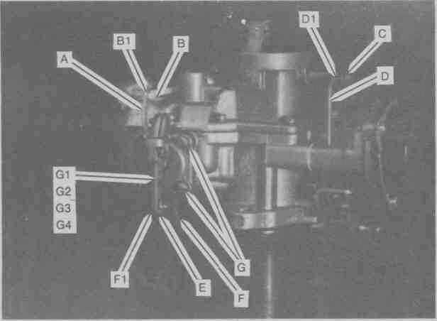
Fig. 1 |
|
| Step 1 | Remove Clip A (Fig. 1); release link B at that point. (On some models, this linkage is released by removing a screw at the lower end where it attaches to the fast idle cam). |
| Step 2 | Remove clip C (Fig. 1); release link D at that point. |
| Step 3 | Remove clip E (Fig. 1); release link F at that point |
| Step 4 | Remove 4 screws G (Fig. 1); Lift off dash-pot cover G1 and remove diaphragm G2 and spring G3 from well G4 . Place spring in bath. Discard diaphragm. |
|
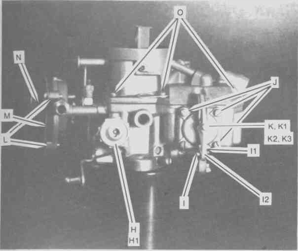
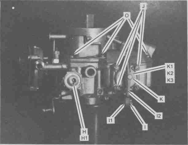
Fig. 2 |
|
| Step 5 | Remove Power valve H (Fig 2) from well H1. Use crescent wrench or 1" open end wrench. Discard valve. |
| Step 6 | Remove spring clip I (Fig 2) and release linkage I1 from lever I2. |
| Step 7 | Remove 4 screws J (Fig. 2); Lift off accelerator pump cover K and remove diaphragm K1 and spring K2 from well K3; Place spring in bath; Discard diaphragm. |
| Step 8 | Remove 3 screws L (Fig 2), retainer ring M, and choke housing N. Do NOT place in bath. |
| Step 9 | Remove 8 bowl cover screws O (Fig. 2); lift cover off carburetor bowl. Discard gasket. |
|
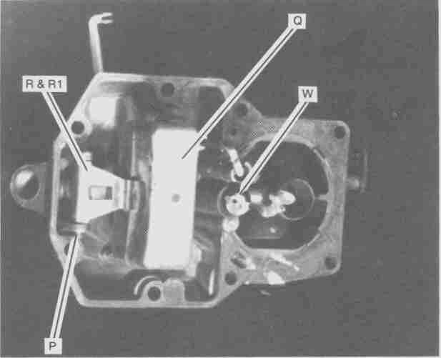
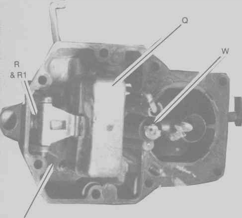
Fig. 3
|
|
| Step 10 | Remove float hinge pin P (Fig. 3) and lift float Q. Do NOT place in bath. |
| Step 11 | Remove needle valve R (Fig. 3) from seat R1; Discard valve. |
| Step 12 | Place bowl cover in bath. |
|
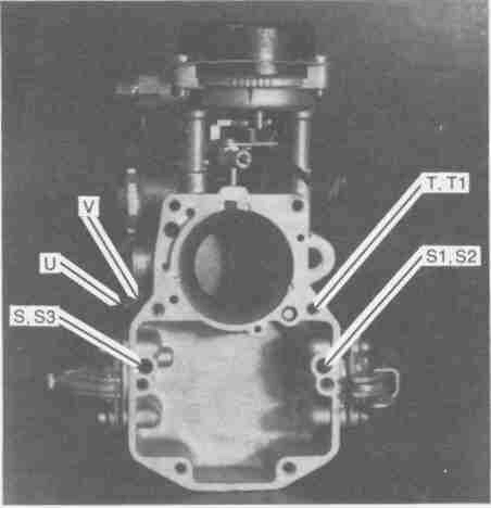
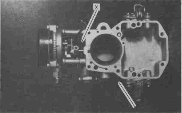
Fig. 4
|
|
| Step 13 | Gently turn over carb your hand and allow balls S2 and S3 (Fig.4) to fall from wells S, S1 and weight T from well T1 to fall out. Discard the balls. Place weight T1 in bath. |
| Step 14 | Remove idle-mixture adjustment screw U (Fig. 4) and spring V; Place both in bath. |
| Step 15 | Place carburetor bowl in bath. |
|
|
Reassembly
| Step 16 | Install idle-mixture adjustment screw U (Fig. 4) into spring V; Run screw into well V1 until it seats lightly, then back it out 1-1/2 (1.5) turns |
| Step 17 | Drop new steel ball T2 (Fig. 4) into well T; Place weight T1 on top of ball. |
| Step 18 | Drop new steel balls S2 and S3 (Fig. 4) into wells S and S1. |
|
Fig. 5
|
|
| Step 19 | Drop new needle valve R (Fig. 5), point first into seat R1. |
| Step 20 | Re-install float Q (Fig. 5) into bowl cover with hinge pin P. |
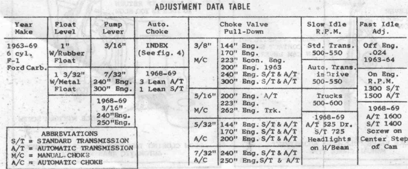
| Step 21 | Adjust float level. (click HERE for procedure) |
| Step 22 | Insert & tighten jet W (Fig. 5) |
| Step 23 | Properly place new gasket into proper position on bowl (Do NOT use gasket sealent) |
Fig. 6
 |
|
| Step 24 | Lower bowl cover into position and carefully attach wth 8 screws O (Fig. 6). Tighten screws lightly and alternating sides/ends to ensure a tight fit and that no damage occurs to gasket. |
| Step 25 | Install new diaphragm K1 (Fig. 6) and tapered coil spring K2 into accelerator pump well K3. (Install spring point-first then place diaphragm over spring with "button" out). |
| Step 26 | Install acellerator pump cover K (Fig. 6) with 4 screws J. Ensure that screws are aligned with diaphragm; Tighten screws. |
| Step 27 | Attach linkage I1 (Fig. 6) to lever I2 with clip I. |
| Step 28 | Place new gasket on power valve (H) (Fig. 6) and thread in new power valve. Use 1" wrench or crescent wrench, being careful to not round faces. |
Fig. 7
 |
|
| Step 29 | Place new diaphragm G2 (Fig. 7), "button" side out, over big end of tapered spring G3, then insert both into dash-pot well G4, spring first. |
| Step 30 | Place dash-pot cover G1 (Fig. 7) into position with lever hinge toward top of carburetor; install 4 metal screws G. Be sure screws are aligned with diaphragm; Tighten screws. |
| Step 31 | Attach linkage F (Fig 7) at point F1 with clip E. |
| Step 32 | Attach linkage D (Fig. 7) at point D1 with clip C. |
| Step 33 | Attach linkage B (Fig. 7) at point B1 with clip A. |
| Step 34 | Install carburetor on engine. Carefully secure fuel and vacuum line and linkages. |
| Step 35 | Start engine. Allow it to warm up until it runs with choke butterfly in carb throat is wide open; |
|
Fig.8
|
|
| Step 36 | Adjust idle to desired speed with screw X (Fig 8). |
| Step 37 | Adjust idle mixture by turning screw U (not X in Fig 8...the OTHER one) clockwise until engine begins to run rough, then counter-clockwise until smooth idle is acheived. |
.jpg)
.jpg)
.jpg)
.jpg)