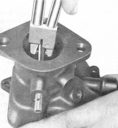
FIGURE 18 - STAKING THROTTLE PLATE SCREWS
are aligned with the edges of the slot adjacent to the countersunk holes in the shaft for the two throttle plate screw heads. Install the two new throttle plate screws snugly, but do not tighten.
Turn the throttle shaft to check for binding. If the throttle plate moves freely from the closed to the wide open positior, tighten the two throttle plate screws and stake the tips to prevent loosening, using Manzel Tool No. 9586. If binding is noticed, tap the upper body casting with a fiber mallet and recheck.
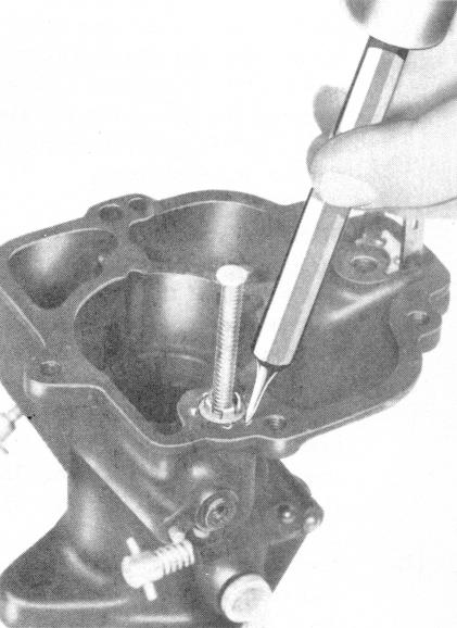
FIGURE 19 - STAKING ECONOMIZER PISTON AND STEM ASSEMBLY
(3) Install the throttle stop lever on the throttle shaft. Be sure the pin holes in the lever and the shaft are aligned and that the two holes for the pump link adjustment are toward the fuel inlet. Drive the pin into position with a small hammer. Install the throttle stop screw and spring.
(4) Install the new pump link in the hole in the throttle stop lever nearest the throttle shaft for normal climatic conditions, or in the hole nearest the end of the throttle stop lever if continuous
of the pump well in the lower body casting.
(11) Install the pump rod extension, slotted end up, in the lower body casting. Install the pump rod pin which links the lower ends of the pump rod and the pump rod extension.
b. Reassembly - Upper Body
(1) Install the distributor passage plug in the upper body casting.
(2) Place a new felt seal on the throttle shaft and slide the throttle shaft into position in the upper body casting. Turn the throttle shaft so that the slot for the throttle plate is vertical and the fast idle lever on the end of the shaft points toward the fuel inlet. Insert the throttle plate in the slot so that the two lines scribed on the plate at disassembly