extreme cold weather operation is anticipated. Install the throttle lever with the lever arm over the pump link and throttle stop lever, and with the throttle lever ball pointing outward.
which holds the throttle kicker lever in position. Snap the hook on the long end of the spring over the edge of the throttle kicker lever.
Place the spring on the new idle adjusting needle and screw the needle gently into the upper body casting until it is seated. Then back it off three-quarters of a turn. Do not force the needle against the seat, as this will damage the tip of the needle and make it impossible to properly set the idle mixture.
Slide the venturi into position in the upper body, aligning the hole in the wall of the venturi with the hole in the upper body casting for the distributor vacuum passage jet. Place the new gasket on the distributor vacuum passage jet and install the jet, thus locking the venturi in position. Install the distributor vacuum line fitting.
Install the new economizer piston and stem assembly, using Manzel Tool No. 9904-C. Lightly punch each of the stake marks in the upper body casting to insure a secure installation of this assembly.
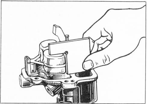
FIGURE 20 - GAUGING FLOAT SETTING
Install the new fuel inlet needle, seat, and gasket assembly. Install the float and lever assembly, using the new float shaft.
Place the upper body assembly upside down on the bench. The floats will drop to the closed position. Place the float gauge as shown in Figure 20. The gauge should just touch the float. Adjust by bending the lever. Check both floats in this manner.
Place the throttle kicker spring over the boss on the side of the upper body casting with the short end of the spring down against the casting, Engage the loop on the short end of the spring with the pin in the casting. Place the throttle kicker lever on the boss with the adjusting screw in the lever touching the flat portion of the fast idle lever on the throttle shaft with the throttle closed. Install the screw and washer
To check the full open setting of the floats, lift them to the full open position. Any accurate depth gauge may then be used to measure the distance from the float to the upper body casting. Adjustment is made by bending the small tab on the float lever.
Consult current Holley specifications for the proper float gauge part number and the correct dimensions for both open and closed float settings.
(5) (6) (7) (8)
(10) (11)
NOTE: