(1) After the floats have been properly set, place the new carburetor body gasket on the upper body assembly so that all holes in the gasket are properly aligned with the corresponding holes in the casting. Holding the throttle kicker lever against the fast idle lever on the throttle shaft, care fully guide the economizer piston stem, pump rod extension, and venturi into the proper holes and press the two major subassemblies together.
(2) Install the five screws and lockwashers holding the two castings together. Secure the identification tag under the screw and lockwasher nearest the air inlet. Before tightening the screws, inspect the gasket to be sure it overlaps evenly on all sides of the castings.
(3) Slide the lower end of the pump link into the slot in the pump rod extension, and install the pin and new cotter which connect these parts.
(4) Back off the throttle stop screw until it no longer touches the idle stop pin in the upper body casting when the throttle is com pletely closed. With the choke plate wide open and the throttle held tightly closed, the clearance between the tip of the fast idle adjusting screw and the throttle shaft fast idle lever must be set between 1/16'' and 1/32".
(5) With the throttle closed, turn the throttle stop screw in until it just touches the idle stop pin.
Then, turn it in exactly half a turn more. This setting and the idle adjusting needle setting are merely preliminary settings which must be re-set after installation on the engine. The carburetor is now completely assembled and ready for installation on the engine.
D. INSTALLATION 1. PREPARATION
a. Before installing a carburetor which has been in storage, make a visual inspection of its exterior to be sure the unit has not been accidentially damaged due to improper storage or mishandling. Be sure the preliminary adjustments of the idle adjusting needle, throttle stop screw, and the fast idle adjusting screw described in the final reassembly instructions have been properly made.
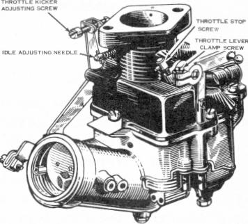
FIGURE 21 - ADJUSTMENTS
b. To prepare the carburetor for installation, loosen the throttle lever clamp screw (Fig. 21) sufficiently to allow the throttle lever to be turned independently of the throttle shaft. Do not loosen the clamp screw excessively - a slight slippage is all that is desired. Next, turn the throttle stop screw (Fig.21) out (counterclockwise)