| |
|
|
|
|
|
|
|
|
|
|
|
|
|
|
|
|
|
|
|
|
9D-3
MODELS 2G-2GC-2GV
PAGE 19
|
|
| |
|
|
|
|
|
|
|
|
|
|
|
|
|
|
|
|
|
|
|
|
|
|
|
|
|
|
|
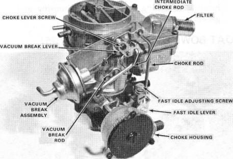
2GV MODELS WITH VACUUM BREAK DIAPHRAGM UNIT(S) (Figure 31)
|
|
|
|
5. If not removed previously, remove fast idle cam attaching screw, then remove fast idle cam. Remove choke rod by rotating until lug on upper end of choke rod passes through slot in the upper choke lever and collar assembly.
|
| |
1. Mount carburetor on proper holding fixture.
|
|
|
|
|
|
|
| |
2. Remove choke coil lever retaining screw from end of choke shaft and remove choke coil lever from choke vacuum break diaphragm rod.
|
|
|
|
| |
|
|
|
|
|
NOTE: The upper end of the choke rod cannot
|
|
|
| |
3. Remove the choke vacuum break diaphragm rod from the vacuum break diaphragm plunger by rotating offset end of rod out of slot in diaphragm plunger.
|
|
|
|
|
|
be removed from the choke shaft on some
|
|
|
| |
|
|
|
|
|
models until after the air horn and choke valve
|
|
|
| |
|
|
|
|
|
are removed.
|
|
|
|
|
|
|
|
|
|
|
|
| |
4. Remove vacuum break diaphragm hose(s) from tube on throttle body.
|
|
|
|
6. Remove idle vent valve and shield (if used) by removing small attaching screw. On Chrysler 2GV models, remove cover, gasket, spring, and idle vent valve.
|
| |
5. Remove two retaining screws and remove vacuum break
|
|
|
|
| |
|
diaphragm and bracket assembly from air horn. NOTE: On 2GV models that use two vacuum break diaphragm assemblies, the main (primary) vacuum break diaphragm unit on the throttle lever side is removed by rotating the vacuum break rod until the end slides out of slot in lever and lug on other end of rod out of slot in end of diaphragm plunger shaft.
|
|
|
|
|
|
7. Remove the (8) air horn attaching screws, then carefully lift the air horn straight up to remove.
|
| |
|
|
|
|
|
|
8. Place air horn inverted on a clean, flat surface.
|
|
|
|
|
| |
|
|
|
|
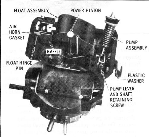
AIR HORN ASSEMBLY (Figure 33)
|
|
|
|
|
|
| |
|
|
|
|
|
|
|
|
|
|
|
|
|
|
|
|
|
|
|
|
| |
|
|
|
|
 |
|
| |
|
|
|
|
|
|
|
|
|
|
|
|
| |
|
 |
|
|
|
| |
|
|
|
|
|
|
|
|
|
|
|
|
|
|
|
|
|
|
|
| |
|
|
|
|
|
|
|
|
|
FIGURE 33
|
|
|
|
|
|
|
| |
|
|
|
|
|
|
|
|
|
|
|
|
|
|
|
|
|
|
|
|
|
|
|
| |
|
|
|
|
|
|
|
|
|
|
|
|
|
9. Remove the float hinge pin and float assembly.
|
|
|
|
|
| |
|
|
|
|
|
|
|
|
|
|
|
|
10. Remove float needle, pull clip (if used); then remove
|
| |
|
|
|
FIGURE 32
|
|
|
|
|
|
|
|
| |
|
|
|
|
|
|
|
|
|
|
|
|
float needle seat and gasket using tool BT-3006.
|
|
|
|
| |
|
|
|
|
|
|
|
|
|
|
|
|
11. Remove air horn to float bowl gasket, and metal needle
|
ALL MODELS
|
|
|
|
|
|
|
|
|
|
|
|
|
seat baffle (if used).
|
|
|
|
|
|
|
|
|
|
| |
I . Mount carburetor on holding stand.
|
|
|
|
|
|
|
|
|
|
NOTE: On some models, the baffle is staked to the air horn and must not be removed.
|
|
|
| |
2. Remove fuel inlet nut, fuel filter, filter relief spring and
|
|
|
|
|
|
|
|
| |
|
gaskets. Note position of filter for later reassembly. If
|
|
|
12. Remove power piston assembly (if used) by depressing
|
| |
|
no integral fuel filter is used in air horn, remove fuel
|
|
|
|
|
shaft and allowing spring to snap, thus forcing piston
|
| |
|
inlet fitting, gasket, and inlet screen.
|
|
|
|
|
|
|
|
|
retainer from casting. This procedure may have to be
|
| |
3. Remove pump rod from pump lever by removing clip.
|
|
|
|
|
repeated several times.
|
|
|
|
|
|
|
|
|
| |
|
If no clip is used, leave rod in pump lever for later
|
|
|
|
|
|
NOTE: If heavy staking is encountered, remove staking from around power piston retaining washer. Use care not to bend the power piston stem.
|
|
|
| |
disassembly after air horn is removed from float bowl. 4. Remove lower end of pump rod from throttle lever
|
|
|
|
|
|
|
|
| |
|
after removing retaining clip.
|
|
|
|
|
|
|
|
|
|
|
|
|
|