| |
|
|
|
|
|
|
|
|
|
|
|
|
|
|
|
|
|
|
|
|
|
|
9D-3
|
|
|
|
|
|
|
|
|
|
|
|
|
|
|
|
|
|
|
|
|
|
MODELS 2G-2GC-2GV PAGE 20
|
|
|
|
|
|
|
|
|
|
|
|
|
|
|
|
|
|
|
| |
|
|
|
|
|
|
|
|
|
|
|
|
|
|
|
|
|
|
|
|
|
|
| |
|
|
|
|
|
|
|
|
|
|
|
|
|
|
|
|
|
|
|
|
|
|
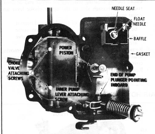
AIR HORN ASSEMBLY (Fig. 34)
|
|
|
|
16. If used, remove seal from end of choke valve shaft.
|
|
| |
|
|
|
|
|
|
|
|
|
|
|
|
|
CAUTION: Do not immerse the seal in car
|
|
|
| |
|
|
|
|
|
|
|
|
|
|
|
|
|
buretor cleaner. Cleaning solution will cause the
|
|
|
 |
|
|
|
|
|
|
|
| |
|
|
|
|
seal to swell or distort.
|
|
|
|
|
|
|
| |
17. On certain California 2GV models, remove the interna vent valve from inside the air horn casting by removing (4) diaphragm housing retaining screws. Then, lif housing and diaphragm assembly gently from casting remove diaphragm spring.
|
| |
18. If the choke valve or shaft needs replacement (Figur( 34), remove the (2) choke valve attaching screws (fil( off staked ends of screws); then remove the choke valy( and choke shaft from the air horn. Remove uppe choke lever and choke rod assembly from choke shaf by sliding off end of shaft, noting position of the uppe choke lever in relation to the choke trip lever on end o choke shaft for ease in reassembly.
|
| |
|
|
|
|
CAUTION: The choke shaft may be teflon coated; sanding, wire brushing, or filing will destroy the coating.
|
|
| |
|
|
|
|
NOTE: On early 2GC units where the choke piston and lever asembly is riveted to choke shaft, rotate choke shaft to free choke piston from bore and remove choke shaft, lever and piston assembly. Then remove (2) choke housing attaching screws, choke housing and gasket.
|
|
| |
|
|
|
|
|
|
|
|
|
|
|
|
|
|
| |
|
|
|
|
FIGURE 34
|
|
|
|
|
|
|
|
|
|
| |
13. Remove retainer clip (if used) from end of pump plunger shaft (Figure 34); then remove pump assembly from inner pump arm. If no clip is used, remove the inner pump lever from pump lever shaft in air horn by loosening set screw; then remove pump plunger assembly from inner pump arm by rotating the pump assembly until the end of shaft will slide out of hole in inner pump lever.
|
|
|
|
|
|
|
| |
|
|
|
|
|
|
|
|
|
|
|
|
|
|
| |
|
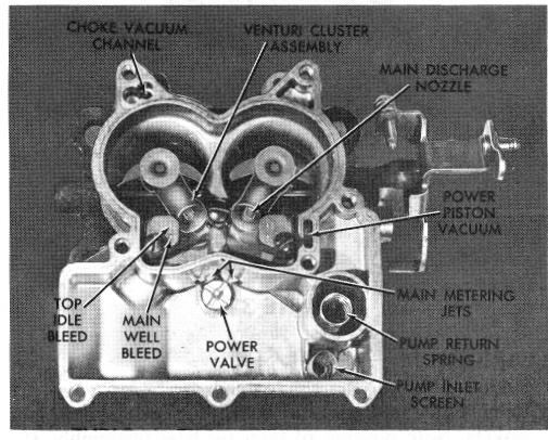
FLOAT BOWL DISASSEMBLY (Fig. 35)
|
|
|
|
| |
|
 |
| |
|
|
NOTE: On some pump plunger applications, the end of the shaft is "upset" in manufacturing to provide the "clipless" retaining feature. On these applications, with small pliers twist the flattened upset at end of shaft until it breaks to permit removal of the pump assembly from inner lever.
|
|
|
| |
14. If the pump lever and shaft or inner arm has not been removed, loosen set screw on the inner arm (Figure 33, page L9) and remove inner arm from pump shaft. The outer pump lever and shaft assembly may now be removed from the air horn.
|
|
| |
|
|
CAUTION: Do not bend retaining ear on inner lever which holds the pump plunger assembly into the lever. Always remove the inner lever first and rotate the pump plunger assembly ("clipless" type) out of the inner lever. If the retaining tang on the inner pump lever is bent, throttle sticking can result.
|
|
|
| |
|
|
|
|
|
|
|
|
|
|
FIGURE 35
|
|
|
|
|
|
| |
|
|
|
|
|
|
|
|
|
|
|
|
|
|
|
|
|
| |
|
|
|
|
FLOAT BOWL DISASSEMBLY - (Figure 35)
|
|
|
|
|
| |
|
|
|
|
|
1. Remove accelerator pump return spring from pump
|
| |
|
|
NOTE: A plastic washer may be used between the outer pump lever and air horn casting. Do not immerse the washer in carburetor cleaner.
|
|
|
|
|
|
well.
|
|
|
|
|
|
|
|
|
| |
|
|
|
|
|
|
|
|
NOTE: On carburetors using pump inlet channel in bottom of pump well, removed small aluminum inlet check ball from bottom of pump well and pump inlet screen from bottom of fuel bowl (where used).
|
|
| |
15. If not removed previously, remove choke rod by
|
|
|
|
|
|
|
| |
|
rotating rod in lever to align squirt on rod with hole in
|
|
|
|
|
|
|
| |
|
lever.
|
|
|
|
|
|
|
|
|
|
|
|