| |
|
|
|
|
|
|
|
|
|
|
|
|
|
|
|
|
|
|
|
|
|
9D-3
MODELS 2G-2GC-2GV
PAGE 21
|
| |
|
|
|
|
|
|
|
|
|
|
|
|
|
|
|
|
|
|
|
|
|
|
|
|
|
|
|
|
| |
|
|
|
|
|
|
|
|
|
|
|
|
|
|
|
|
|
|
|
|
|
|
|
|
|
|
|
|
| |
|
|
|
|
|
|
|
|
|
|
|
 |
| |
2. Remove (2) main metering jets.
|
|
|
|
|
|
|
| |
3. Remove power valve (power enrichment valve assembly - Vega) and gasket using tool BT-3007.
|
|
| |
4. Remove (3) venturi cluster attaching screws, then remove cluster and gasket. Center cluster screw has smooth shank for accelerator pump fuel by-pass and fibre sealing washer(s) under screw head in place of lockwasher.
|
|
| |
|
|
NOTE: A high-speed baffle is used under the center cluster screw on some models. Carefully observe the position of the baffle for later reassembly. See step 6, page 24.)
|
|
|
|
| |
5. Remove the main well insert tubes (if used) from the
|
|
| |
|
main wells. Consult the "C" Parts Bulletin in the Delco
|
|
| |
|
9X Manual for application on a particular carburetor
|
|
| |
|
model.
|
|
|
|
|
|
|
|
|
| |
|
|
|
|
|
|
|
|
|
|
|
|
|
|
|
FIGURE 36
|
|
|
|
|
|
|
| |
6. Using a pair of needle-nosed pliers, remove the T-shaped pump discharge retainer guide and remove the spring and steel check ball (larger than pump inlet ball).
|
|
|
|
|
|
|
|
|
|
|
|
|
|
| |
|
|
|
|
|
choke housing and gasket. Remove intermediate
|
| |
|
|
|
|
|
choke shaft and lever from choke housing.
|
|
|
|
|
| |
7. Where used, remove idle air by-pass adjusting screw and spring at rear of float bowl.
|
|
|
|
|
|
|
|
|
|
| |
|
|
|
|
|
NOTE: On units with split choke linkage, it will
|
|
| |
|
|
|
|
|
be necessary to remove the fast idle cam screw,
|
|
| |
8. Remove (2) screws and remove hot idle compensator
|
|
|
|
|
|
|
| |
|
|
|
|
|
then remove cam and choke rod as an assembly.
|
|
| |
|
cover (if used), compensator, and gasket.
|
|
|
|
|
|
|
|
|
|
| |
|
|
|
|
|
|
|
|
|
The fast idle cam and intermediate choke lever
|
|
| |
9. Remove distributor vacuum fitting (where used) from
|
|
|
|
|
|
can be disassembled further by removing clips
|
|
| |
|
float bowl.
|
|
|
|
|
|
|
|
|
|
|
|
|
| |
|
|
|
|
|
|
|
|
|
|
|
|
on ends of choke rod.
|
|
|
|
|
|
|
|
|
10. Remove vacuum hose from the Combination Emission Control valve (C.E.C. valve), if used, and from the vacuum tube on the throttle body.
|
|
|
|
|
|
|
|
|
|
|
|
|
|
| |
|
|
2GC MODELS WITH VACUUM BREAK UNIT
|
|
|
|
| |
|
|
a. Remove the (3) choke cover attaching screws and
|
| |
|
|
|
|
retainers, then remove cover and coil assembly and
|
11. On models using a C.E.C. valve or idle stop solenoid mounted on the carburetor, bend back retaining tabs on lockwasher; then remove large C.E.C. valve or idle stop solenoid nut and remove valve or solenoid from bracket.
|
|
|
|
|
|
| |
|
|
|
|
gasket.
|
|
|
|
|
|
|
|
|
|
|
|
|
| |
|
|
b. Remove baffle plate from inside choke housing.
|
|
| |
|
|
c. Remove the (2) choke housing attaching screws,
|
| |
|
|
|
|
then remove choke housing and gasket from throt
|
| |
|
|
|
|
tle body casting.
|
|
|
|
|
|
|
|
|
|
|
| |
|
|
NOTE: Do not remove the bracket for the C.E.C. valve or idle stop solenoid from the float bowl unless replacement of the bracket is necessary.
|
|
|
|
|
|
|
|
|
|
|
|
|
|
|
|
|
|
| |
|
|
|
|
|
|
|
d. On back side of housing remove screw from end of
|
| |
|
|
|
|
|
|
|
|
|
intermediate choke shaft, then remove intermediate
|
| |
|
|
|
|
|
|
|
|
|
choke lever. Remove choke coil lever and shaft
|
| |
|
|
|
|
|
|
|
|
|
assembly from choke housing. Remove dust seal
|
| |
|
|
CAUTION: Do not immerse the C.E.C. valve assembly or idle stop solenoid in any type of carburetor cleaner.
|
|
|
|
|
|
|
|
| |
|
|
|
|
|
|
|
|
|
from choke housing.
|
|
|
|
|
|
|
|
|
|
| |
|
|
|
|
|
|
|
e. The combination fast idle and unloader lever can be
|
| |
|
|
|
|
|
|
|
|
|
removed from end of throttle shaft by removing
|
12. Invert carburetor and remove (3) throttle body to bowl attaching screws. Remove throttle body and throttle body to bowl gasket.
|
|
|
|
|
|
| |
|
|
|
|
attaching screw.
|
|
|
|
|
|
|
|
|
|
|
| |
|
ALL MODELS
|
|
|
|
|
|
|
|
|
|
|
|
|
| |
|
13. Remove slow and fast idle screws (where used) from throttle lever if replacement is necessary.
|
|
|
|
|
|
|
|
|
|
|
|
|
|
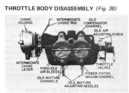
THROTTLE BODY DISASSEMBLY
|
|
|
|
|
|
|
| |
|
|
|
|
|
|
|
NOTE: Do not tamper with idle mixture
|
|
|
| |
|
|
|
|
|
|
|
|
|
|
|
|
|
|
|
|
| |
|
CHOKE HOUSING, WITH CHOKE PISTON, MOUNTED ON THROTTLE BODY - (Figure 36) Disassemble as follows:
|
|
|
|
|
needles that have limiter caps unless performing
|
|
|
| |
|
|
|
|
|
an overhaul or needles are damaged.
|
|
|
|
|
|
| |
|
|
|
14. On 1971 and later 2GC, 2GV models, the idle mixture needles have been preadjusted and set at the factory and capped, to prevent readjustment in the field. If it is necessary to remove the idle mixture needles for cleaning purposes, remove the original plastic caps and destroy, and readjust the idle mixture per recommended instructions by the vehicle manufacturer. IMPORTANT: Before removing the idle mixture needle, it is suggested count the number of turns to bottom the old mixture needle. Then, when installing a
|
| |
|
a. Remove choke cover and coil assembly by removing (3) choke cover attaching screws and retainers. Remove choke cover gasket.
|
|
|
| |
|
b. Remove baffle plate from inside choke housing.
|
|
|
|
| |
|
c. Remove choke piston, lever and link assembly from intermediate choke shaft by removing attaching screw in end of shaft. Choke piston can be removed from lever and link by shaking piston pin into hand.
|
|
|
| |
|
d. Remove (2) choke housing attaching screws, remove
|
|
|