tubes. On some models, the fuel is mixed with air at the top of each idle tube through an idle air bleed. The air bleed size is controlled either by a drilled hole or a brass insert depending on the carburetor application.
NOTE: No attempt should be made in the field to install a brass insert in those applications that use a drilled hole for the idle air bleed.
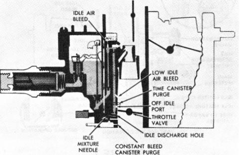
Then the fuel mixture crosses over to the idle down channels where it is mixed with air at the side idle bleed located just above the idle channel restriction. The mixture continues down through the calibrated idle channel restrictions past the lower idle air bleeds and off-idle discharge ports where it is further mixed with air. The air/fuel mixture moves down to the adjustable idle mixture needle discharge holes where it enters the carburetor bores and blends with the air passing the slightly open throttle valves. The combustible air/fuel mixture then passes through the intake manifold to the engine cylinders.
The idle mixture needles are adjustable to blend the correct amount of fuel mixture from the idle system with the air entering the engine at idle.
Turning the idle mixture needles inward (clockwise) decreases the idle fuel discharge (gives a leaner mixture) and turning the mixture needles outward (counterclockwise) enriches the engine idle mixture. Some carburetor models have a fixed idle air by-pass system. This consists of air channels which lead from the top of each carburetor bore in the air horn to a point below each primary throttle valve. At normal idle, extra air passes through these channels supplementing the air passing by the slightly opened throttle valves. The purpose of the idle air by-pass system is to allow reduction in the amount of air going past the throttle valves so they can be nearly closed at idle. This reduces the amount of air flowing through the carburetor venturi to prevent the main fuel nozzles from feeding during idle operation. The venturi system is very sensitive to air flow and on some applications where larger amounts of idle air are needed to maintain idle speed, the fixed idle air by-pass system is used.
On exhaust emission control carburetor applications, the idle mixture needle discharge holes have been reduced in size. This was done to prevent a too rich idle adjustment in the field should the idle mixture needles be turned out too far beyond normal idle mixture requirements. Also, starting in 1971, idle needle limiter caps were added to emission control carburetors to discourage adjustment of the needles in the field.
Another feature added to some emission carburetors is an adjustable off-idle air bleed system (Figure 5). A separate air channel is added in the air horn which leads from the top of the air horn to the idle mixture cross channel. An adjustment screw with a tapered head is mounted at the top of the channel and is used to control the amount of air bleeding into the idle system. The off-idle
air bleed is adjusted at the factory to maintain very accurate off-idle air/fuel mixture ratios. It is adjusted during carburetor flow test and no attempt should be made to readjust in the field. A triangular spring clamp forced over the vent tube covers the screw to protect the adjustment from being tampered with and should not be removed. All service air horns have this screw preset at the factory.
OFF-IDLE OPERATION
As the primary throttle valves are opened from curb idle to increase engine speed (See inset - Figure 5), additional fuel is needed to combine with the extra air entering the engine. This is accomplished by the slotted off-idle discharge ports. As the primary throttle valves open, they pass by the off-idle ports, gradually exposing them to high engine vacuum below the throttle valves. The additional fuel added from the off-idle ports mixes with the increasing air flow past the opening throttle valves to meet increased engine air and fuel demands.
Further opening of the throttle valves increases the air velocity through the carburetor venturi sufficiently to cause low pressure at the lower idle air bleeds. As a result, fuel begins to discharge from the lower idle air bleed holes and continues to do so throughout operation of the part throttle to wide open throttle ranges, supplementing the main discharge nozzle delivery.
The idle needle holes and off-idle discharge ports continue to supply sufficient fuel for engine requirements until air velocity is high enough in the venturi area to obtain efficient fuel flow from the main metering system.
IDLE SYSTEM (Fig. 6)
FIGURE 6
Certain 1970 and all 1971 and later G.M. model cars and light-duty trucks have completely closed fuel tank venting to control evaporative emissions. The vent from the fuel tank leads into a vapor collection canister.