to maintain an internally balanced carburetor. This is accomplished through the spring steel vent valve arm which operates off the wire lever on the end of the pump lever. As the throttle valves are opened from the idle position, the vent arm exerts pressure on the bi-metal strip and forces the valve closed.
The thermostatic vent valve is adjustable to make sure it closes at the proper time during throttle valve opening from the idle position.
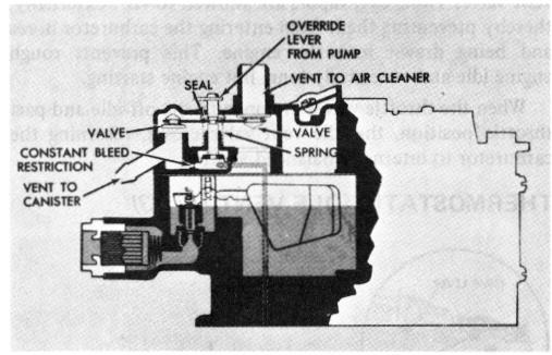
VACUUM VENT SWITCH
(ENGINE OFF CONDITION) (Fig. 4)
FIGURE 4
Some Quadrajet carburetors have the float chamber internally vented through a vacuum vent switch valve mechanism (Figure 4) located in the top of the air horn casting to function with the Evaporative Loss System Vapor Canister. During engine operation, manifold vacuum applied to a diaphragm in the air horn casting pulls downward on a diaphragm piston which opens the internal float bowl vent to the air cleaner. This maintains an internal balance between the air entering the carburetor bore and the fuel in the float bowl. The vacuum vent switch valve mechanism in the carburetor air horn is designed so that during periods of shutdown, when the engine is hot, fuel vapors from the float bowl are vented directly to the vapor collection canister instead of the atmosphere. This is accomplished by a spring beneath the vacuum diaphragm piston which, when the engine is shut down, forces the piston upward closing off the vent to the air cleaner and opening a vent which leads to the vapor canister. Along with the vent system, a feature is incorporated to keep the internal vent system open during high speeds and heavy acceleration when manifold vacuum is low. An actuating arm attached to the pump lever actually pushes downward on the internal vent valve and holds it open when vacuum beneath the vent valve diaphragm is not great enough to hold it open. This maintains internal carburetor balance at all times when the engine is running. A restriction, located in a passage beneath the diaphragm piston cavity in the air
horn, provides a constant purging of fuel vapors from the vapor canister during engine operation.
NOTE: External venting is not used on Quadrajet carburetors designed for marine use or for use with the Evaporation Control System (E.C.S.).
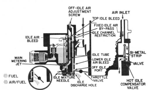
IDLE SYSTEM
IDLE SYSTEM (Fig. 5)
OFF- IDLE OPERATION
FIGURE 5
The Quadrajet carburetor has an idle system on the primary side (fuel inlet side) of the carburetor to supply the correct air/fuel mixture ratios during idle and off-idle operation. The idle system is used during this period because air flow through the carburetor venturi is not great enough to obtain efficient metering from the main discharge nozzles. The idle system is only used in the two primary bores of the carburetor. Each bore has a separate and independent idle system.
During curb idle, the throttle valves are held slightly open by the idle speed adjusting screw or solenoid plunger screw. The small amount of air passing between the primary throttle valves and bores is regulated by this screw or plunger to give the engine the desired idle speed. Since the engine requires very little air for idle and low speeds, fuel is added to the air to produce a combustible mixture by the direct application of vacuum (low pressure) from the engine manifold to the idle discharge holes below the throttle valves. With the idle discharge holes in a very low pressure area and the fuel in the float bowl vented to atmosphere (high pressure), the idle system operates as follows:
Fuel flows from the float bowl down through the main metering jets into the main fuel wells. It is picked up in the main wells by the two idle tubes (ones for each primary bore) which extend into the wells. The fuel is metered at the lower tip of the idle tubes and passes up through the