secondary bores. Its purpose is to offset the enriching effects caused by excessive fuel vapors during hot engine operation.
The compensator consists of a thermostaticallycontrolled valve, a heat sensitive bi-metal strip, and a valve holder and bracket. The compensator valve assembly is held in place by a dust cover over the valve chamber. A seal is used between the compensator valve and the float bowl casting. The valve closes off an air channel leading from a hole in the top of the air horn, just beneath the air cleaner, to a point below the secondary throttle valves.
Normally, the compensator valve is held closed by tension of the bi-metal strip. During extreme hot engine operation, excessive fuel vapors entering the engine manifold cause richer than normally required mixtures, resulting in rough engine idle and stalling. At a predetermined temperature, when extra air is needed to offset the enriching effects of these fuel vapors, the bi-metal strip bends and unseats the compensator valve. This uncovers the air channel leading from the valve chamber to the point below the throttle valves. This allows enough air to be drawn into the engine manifold to offset the richer mixtures and maintain a smooth engine idle. When the engine cools and the extra air is not needed, the bi-metal strip relaxes, closes the valve, and operation returns to normal mixtures.
For proper idle adjustment when the engine is hot, the compensator valve must be closed. To check this, a finger may be held over the compensator air inlet channel located on top of the air horn. If no drop in engine RPM is noted on a tachometer, the valve is closed. If the valve is open, plug the hole or cool engine down to a point where the valve automatically closes for proper idle adjustment.
NOTE: Plug the compensator hole with a pencil or something that will be seen, as the plug must be removed before the air cleaner is installed. Otherwise the compensator will not function if the plug is left in the hole.
NOTE: On some applications, the air inlet to the hot idle compensator is located beneath the air valve in the secondary bores (View B). The air inlet in this location improves idle quality when the hot idle compensator valve is open. The compensator valve can be checked for proper closing during idle adjustment by pushing inward on a spring-loaded plunger mounted in the idle compensator cover. The idle adjustment procedure is the same as recommended previously.
On some Model 4MV carburetors, the Hot Idle Compensator is located on the primary side of the float bowl (View A). It is mounted in the bowl with a pin protruding through the air horn casting to facilitate closing the valve when the idle adjustment is made. The air inlet for the compensator is located in the cavity next to the choke rod in the bowl.
When the compensator opens, filtered air is drawn around the choke rod through a passage in the float bowl an( throttle body and on into the intake manifold. The air enters the manifold through the opening in between the primary bores. This air mixes with the air/fuel mixture during hot engine operation.
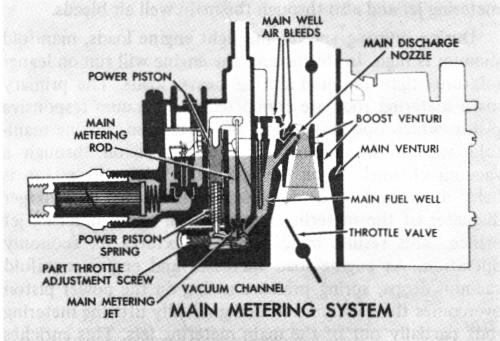
MAIN METERING SYSTEM
MAIN METERING SYSTEM (Fig. 9)
FIGURE 9
The main metering system (Figure 9) supplies fuel to the engine from off-idle to wide-open throttle. The primary bores (two smaller bores) supply fuel and air during this range through plain tube nozzles and the venturi principle.
The multiple venturi in each primary bore produce excellent fuel metering control due to their sensitivity to air flow.
The main metering system begins to operate as air flow increases through the venturi system and additional fuel is needed to supply the correct air/fuel mixture to the engine. Fuel from the idle system gradually diminishes as the lower pressures are now in the venturi system.
The main metering system consists of main metering jets, vacuum operated primary metering rods, main fuel wells, main well air bleeds, main discharge nozzles, triple venturi, fuel pull-over enrichment (some applications), adjustable part throttle (some applications).
As the primary throttle valves are opened beyond the off-idle range allowing more air to enter the engine intake manifold, air velocity increases in the carburetor venturi. This causes a drop in pressure in the large venturi which increases many times in the boost venturi. Since the low pressure (vacuum) is now in the smallest boost venturi, fuel flows from the main discharge nozzle as follows:
Fuel from the float bowl flows through the main metering jets into the main fuel wells. It passes upward in the main well and is bled with air by an air bleed located at