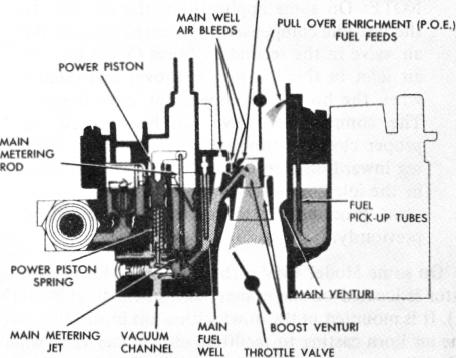
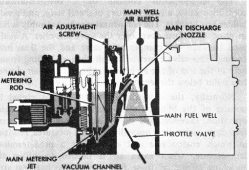
the top of well. The fuel is further bled air through calibrated air bleeds located near the top of the well in the carburetor bores. The fuel mixture then passes from the main well through the main discharge nozzles into the boost venturi. At the boost venturi, the fuel mixture then combines with the air entering the engine through the carburetor bores. It then passes as a combustible mixture through the intake manifold and on into the engine cylinders. The main metering system is calibrated by tapered and stepped metering rods operating in the main metering jet and also through the main well air bleeds.
During cruising speeds and light engine loads, manifold vacuum is high. In this period, the engine will run on leaner mixtures than required during heavy loads. The primary main metering rods are connected to a vacuum responsive piston which operates against spring tension. Engine manifold vacuum is supplied to a power piston through a vacuum channel. When the vacuum is high, the piston is held downward against spring tension and the larger diameter of the metering rod is in the main metering jet orifice. This results in leaner fuel mixtures for economy operation. As engine load increases and engine manifold vacuum drops, spring pressure acting on the power piston overcomes the vacuum pull and gradually lifts the metering rods partially out of the main metering jets. This enriches the fuel mixture enough to give the desired power required to overcome the added load.
ADJUSTABLE PART THROTTLE FEATURE
Some exhaust emission control carburetor models have an adjustable part throttle feature (Figure 9) used in production to maintain a very close tolerance of fuel mixtures during part throttle operation. This includes a special power piston and primary main metering rods. The piston has a pin pressed into its base which protrudes through the float bowl and gasket and contacts an adjustable link in the throttle body. The metering rods are tapered at the upper metering end, so that fuel flow through the main metering jets is controlled by the depth of the taper in the main metering jet orifice. During production, the adjustable part throttle screw is turned in or out to place the taper at the exact point in the jet orifice to obtain the desired air/fuel mixture ratio. Once set, the adjustment screw is capped and no attempt should be made to readjust it in the field.
The tapered metering rod used with the adjustable part throttle feature can be identified by the Suffix "B" after the part number stamped on the side of the rod.
Whenever the throttle body of a Quadrajet with the Adjustable Part Throttle (A.P.T.) feature is replaced, the A.P.T. screw should be adjusted as specified in the instruction sheet included with Rochester Service Replacement Throttle Body Assemblies (Also see step l.d, page 30.).
ADJUSTABLE MAIN WELL AIR BLEED
FEATURE (Fig. 10)
FIGURE 10
Some exhaust emission control carburetors use an adjustable main well air bleed system, replacing the Adjustable Off-Idle (A.O.I.) air bleed, for more accurate fuel control during part throttle operation (Figure 10). The adjustable part throttle air bleed system supplements the other main well air bleeds. The adjustable part throttle air bleed screw refines fuel mixtures to meet exhaust emission control requirements. The screw is adjusted at the factory during carburetor flow test and no attempt should be made to readjust in the field. A triangular spring clamp forced over the vent tube covers the screw to protect the adjustment from being tampered with and should not be removed. All service air horns have this screw preset at the factory.
FUEL PULL-OVER ENRICHMENT (Fig. 11)
MAIN DISCHARGE NOZZLE
FIGURE 11