Delco
9D-5
MODELS 4M-4MC-4MV
PAGE 5
Fuel flow through the diaphragm assisted float needle valve varies from the conventional float needle. With the conventional type as shown on the left in Figure 2, fuel flows from the inlet filter and inlet channel up through the needle seat orifice past the float needle valve and spills over into the float bowl. With the diaphragm type float needle valve, fuel from the inlet filter enters the channel above the float valve tip. When fuel level is low in the bowl, the needle valve is off its seat and fuel flows down past the float valve tip into a fuel channel which leads upward through the bowl casting to a point above normal liquid level and spills over into the float bowl.
The diaphragm type needle valve differs in operation from the conventional float needle in that a larger needle seat orifice can be used to provide greater fuel flow to the float chamber and yet allow the use of a small float. This is accomplished through a balance of forces acting on the float needle valve and diaphragm against fuel pump pressure. Fuel pressure entering the float needle valve chamber tends to force the needle valve closed. However, the same pressure is also acting on the float needle diaphragm. The diaphragm has a slightly larger area than the float needle valve head, therefore the greater pressure acting on the diaphragm tends to push the needle valve off its seat. The force of the float arm acting on the needle stem, as the float bowl fills, overcomes this pressure difference and closes the needle valve. Therefore, the float's function is to overcome the pressure difference and it does not have to force a needle valve closed against direct fuel pump pressure as does the conventional needle type.
NOTE: If desired, certain Quadrajet models may be converted from the diaphragm type needle and seat to the conventional float needle and seat by installing a service modification kit. Refer to 9C Parts Section of the Delco Carburetor 9X Manual for specific applications and part number.
The conventional float needle seat on some Quadrajet carburetors has holes or "side windows" in its side whose purpose is to supplement fuel delivery past the float needle valve when it opens, whereas the "side windows" have been removed on some float needle seat applications so that all fuel will be discharged over the top of the needle seat assembly. Removal of the "side windows" improves operation of the float needle on some applications.
Some conventional float needle seats are nickel plated and use a double angle seat. The double angle seat, along with use of a less resilient viton tip float needle, aids in preventing the float needle from possibly sticking in the seat due to fuel gum formation.
The carburetor float chamber is internally vented on all models through a vent tube or tubes located in the air horn. The internal vent tube(s) leads from beneath the air cleaner to the float bowl chamber. The purpose is to balance air pressure acting on the fuel in the bowl with air flow through the carburetor bores. In this way, balanced air/fuel
mixture ratios can be maintained throughout all carburetor ranges of operation.
Some engine applications require an external vent into the float bowl during hot engine operation. The Quadrajet float bowl is externally vented through an idle vent valve. Its purpose is to vent fuel vapors which may form in the float bowl during periods of hot engine idle and "hot soak."
In operation, the idle vent valve is closed except when the throttle valves are in the idle position. When the throttles are closed, a wire tang on the pump lever pushes upward on the spring steel vent valve arm and opens the vent valve. Thus, fuel vapors are allowed to vent externally, thereby preventing them from entering the carburetor bores and being drawn into the engine. This prevents rough engine idle and excessively long, hot engine starting.
When the throttle valves are open to the off-idle and part throttle position, the idle vent valve closes, returning the carburetor to internally balanced venting.
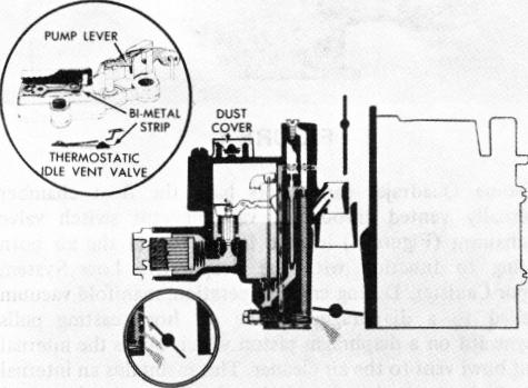
THERMOSTATIC IDLE VENT (Fig. 3)
FIGURE 3
A temperature controlled idle vent valve is used on some models (Figure 3). In place of the standard vent valve; a heat sensitive bi-metal strip is used as the valve holder. This is mounted beneath the idle vent valve arm.
The bi-metal strip holds the vent valve on its seat (closed) at temperatures below 75°. When underhood temperatures are above 75° to 85° the bi-metal strip bends upward moving the vent valve off its seat. This lets fuel vapors, caused during hot engine operation, escape from the float chamber. This results in improved hot engine idle and hot starting. At temperatures below 75°, the vent valve remains closed and retains fuel vapors internally to supply extra fuel for good cold engine starting.
During hot engine operation, when the thermostatic vent valve is open, it is necessary to close the valve except at idle