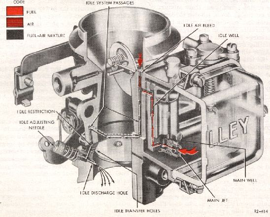
3. MAIN METERING SYSTEM
When the engine is running, the intake stroke of each
piston draws air through the carburetor. As this air
passes through the venturi of the carburetor, the drop
in pressure in the venturi creates what is commonly
called a vacuum. The strength of that vacuum varies in
proportion to the velocity of the air flow through the
venturi. This, in turn, is governed by the speed and
power output of the engine.
At normal cruising speeds, the difference between the
normal, atmospheric air pressure in the float chamber
and the vacuum in the venturi is used to operate the
main metering system. This pressure differential draws
a metered flow of fuel from the float chamber through
the main metering system and out the main nozzle into
the air stream in the venturi. When the fuel passes out
of the float chamber, it is metered (or measured) by the
main jet as it flows into the bottom of the main well.
The fuel moves up the main well past the two
narrow air bleed passages and enters the main nozzle.
Filtered air from the carburetor air inlet enters the air
speed bleed and passing out the two narrow air
bleed passages is mixed with the fuel flow in the
main well. The high speed bleed meters a properly
increasing amount of air into the fuel as speeds
increase, stabilizing the fuel discharge and main-
taining the required mixture ratios. This emulsion of
fuel and air, being lighter than the raw fuel, has a
more instantaneous response to any change in
venturi vacuum and is more readily vaporized than
raw fuel upon being discharged into the air stream.
The fuel flows through the main nozzle and is
sprayed onto the open choke plate in the venturi.
Airstream turbulence over the distribution pin and
choke plate distributes the fuel over the lower
portion of the choke plate where it is vaporized and
mixed with the air flowing through the carburetor.
The throttle plate controls the amount of fuel-air
mixture admitted to the intake manifold, regulating
the engine speed and power output in accordance
with accelerator pedal movement. The distribution
pin extending perpendicularly from both sides of the
choke plate creates a turbulence as an aid to the
proper distribution of the mixture to all cylinders of
IDLE SYSTEM
