

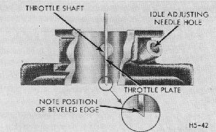
Figure 32. Installing Throttle Plate
of the throttle plate and the throttle bore, and if the
throttle plate moves freely throughout its range of
travel, throttle plate alignment is satisfactory. Hold
the throttle plate in the closed position and tighten the
throttle plate screws.
(2)
Install the new pump link in the throttle lever
with the double bend of the link uppermost. Secure
the pump link in place with one of the new pump link
cotter pins. (The two holes in the throttle permit
adjustments to compensate for climatic conditions;
place the pump link in the hole nearest the throttle
shaft for normal climatic conditions, or use the outer
hole for continuous extreme cold weather operation.)
(3) Install the new idle adjusting needle with its
spring. Turn the needle down gently with the fingers
until it seats, then back it off one full turn. Take care
not to force the needle down on its seat. This will
groove the tip of the needle and make it impossible to
accurately adjust the idle mixture.
(4) On carburetor for automatic transmission
engines, install the dashpot lever, spring, and screw.
B. REASSEMBLY-MAIN BODY
(1)
Place a new gasket on both sides of the pump
discharge nozzle, then insert the pump discharge
nozzle screw into the channeled side of the nozzle.
(The pump discharge nozzle screw may be identified
by the hole drilled vertically from its tip to a point
shortly below the head of the screw, where it joins a
short horizontal drilled passage terminating in a
groove in the side of the screw.) Install the pump
discharge nozzle in the recess at the top of the venturi
in the main body. Allow the pump discharge nozzle to
rotate to the limits of its travel in a clockwise direction
as the nozzle screw is tightened. The nozzle will stop
against the edge of its recess in its proper operating
position after a small amount of rotation.
NOTE
In the List No. 763 and 831 Carburetors,
however, the pump discharge nozzle should
be held in a counter-clockwise position
against the limits of its rotational travel as the
nozzle screw is tightened.
(2)
Position the choke bracket on the boss on the
main body. Slide the choke shaft and lever assembly
into the main body and secure it in place by driving
the choke shaft retainer pin into the small vertical hole
in the top of the choke shaft boss.
(3)
Rotate the choke lever until the choke
lever swivel is below the choke shaft. Insert the
choke plate into the slot in choke shaft with the stem
and spring of the poppet valve extending upward.
CAUTION
Take care not to damage the tip of the main
nozzle while installing the choke plate.
(4)
Center the choke plate to avoid damaging
the venturi then close the choke plate by rotating the
choke lever in a counter-clockwise direction. Install
the choke plate screws, fitting the screw with the
attached lockwasher in the hole nearest the choke
lever. Turn the screws down snugly but not tightly.
Rotate the choke lever until the choke plate is nearly
inverted and the poppet valve stem and spring extend
downward. Align the distribution pin hole in the
choke shaft with the corresponding hole in the choke
plate. Brace the choke shaft from beneath and drive
the distribution pin into position. Install the
distribution pin so the clearance between
.
the tip of
the pin and the venturi wall is equal on both sides
NOTE
The List No. 763 and 831 Carburetors use a
hex-head screw on the side of the choke shaft
nearest the fuel bowl and pump discharge
nozzle. A stem extends above the hex-head
of the screw to facilitate proper fuel
distribution in C.O.E. installations. A
shakeproof external tooth lockwasher is used
to retain the screw. The regular choke plate
screw continues in use as the other plate
screw.