
This completes the disassembly of the main body
assembly. Do not attempt to remove any of the
pressed-in passage plugs, air bleed plugs, or the main
nozzle in the main body,
D. DISASSEMBLY-THROTTLE BODY
ASSEMBLY
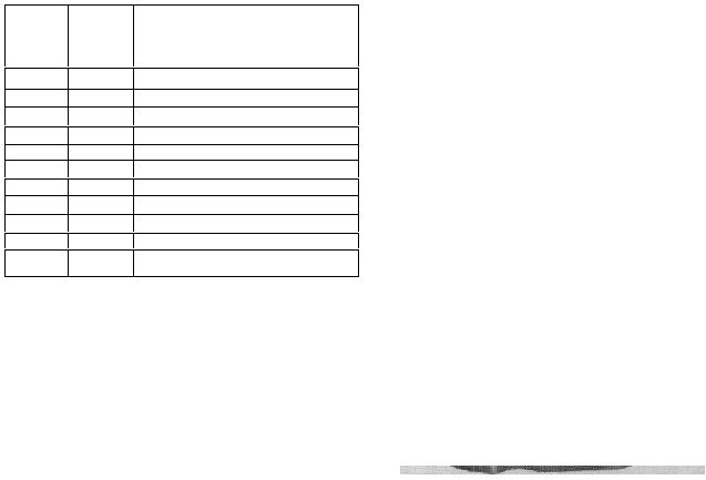
The following list contains all parts removed in
disassembling the throttle body assembly. Parts to be
discarded and replacement made from
a Master Repair Kit are marked with an asterisk (*).
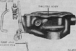
Figure 29. Pump Link and Cotter Pin
REFER TO
FIG. NO.
ORDER OF
REMOVAL
PART NAME
28
1
Idle Adjusting Needle*
28
2
Idle Adjusting Needle Spring
29
3
Pump Link Cotter Pin*
29
4
Pump Link*
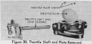
30
5
Throttle Plate Screw and
Lockwasher (2)*
30
6
Throttle Plate
30
7
Throttle Shaft
31
8
Dashpot Lever Screw
31
9
Dashpot Lever Spring
31
10
Dashpot Lever
(4)
Slide the throttle shaft and lever assembly
out of the throttle body.
DASHPOT LEVER
5. CLEANING AND INSPECTION
A. C LEANING
(1)
All castings and metal parts except the
dashpot assembly are to be soaked in a cleaning
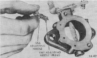
Figure 28. Removing Idle Adjusting Needle
(1)
Remove the idle adjusting needle and
spring. Discard the needle.
(2) Remove and discard the pump link cotter
pin and pump link.
(3)
Scribe the throttle plate along one side of
the throttle shaft to facilitate proper alignment during
reassembly. Remove and discard the two throttle plate
screws and lockwashers. Lift out the throttle plate.
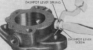
Figure 31. Removing Dashpot Lever Screw
(5)
On carburetors for the automatic trans-
mission engine, remove the dashpot lever screw,
spring, and lever.
This concludes the disassembly of the Car-
buretor Model 1904.