
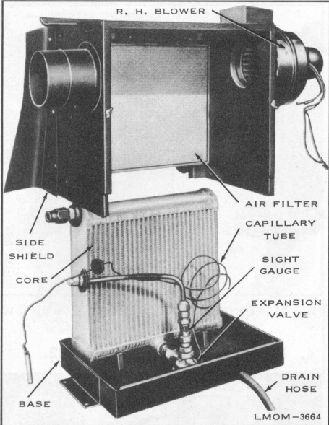
Fig. 28. Evaporator Assembly
5. Roll back rubber shield on low pressure tube
and clip capillary tube in place.
6. Replace flexible duct from L. H. blower to
evaporator.
7. Connect blower wires according to wire colors.
8. If system has been pumped down, open shut off
valves in the following order, with Tool -
ACL53-5. (Turn all valves in the full
counterclockwise direction):
1. Receiver shut off valve.
2. When no more liquid Freon is flowing past
sight gauge, open low pressure valve.
3. Open high pressure valve.
11. To assemble evaporator, reverse removal
procedure. Use new seal when connecting
short section of high pressure hose to sight
gauge.
9.
If system has been exhausted, pres-sure check,
evacuate and charge according to procedure
under "Pres-sure Testing, Evacuating and
Charging System".
10. Replace spare wheel and tire.
1. Position evaporator assembly, with R. H. blower
assembly attached, in the luggage
compartment.
11. Replace rear seat speaker.
2.
3. Remove caps on high pressure tube and fitting on
left side of evaporator assembly. Install new
seal and tighten fitting with Tool - ACL53-6.
Replace four hex head attaching screws
securing evaporator to floor pan and tighten.
The air drawn into the evaporator unit by the
blowers, must first pass through an air filter. This filter
is a permanent type which may be washed in clear
cold water and reused. In washing make sure water
passes through filter in the opposite direction to
normal air flow only. See figure 29.
4. Connect low pressure tube to evaporator fitting
and tighten with Tool - ACL53-7.
In normal operation, the air passing through the filter
in the direction indicated,
causes electrostatic pick up
of
21
INSTALLATION OF EVAPORATOR
ASSEMBLY
REMOVING AIR FILTER